Adaptable recharging and lighting station and methods of using the same

a technology of recharging and lighting stations, applied in the direction of lighting and heating apparatuses with built-in power, semiconductor devices for light sources, lighting and heating apparatus, etc., can solve the problems of inability to recharge, only being used for lighting and charging electronics, etc., to prolong the charging time of batteries, and prevent excessive inrush current

Active Publication Date: 2016-08-04
ELEVATE TECH CORP
View PDF9 Cites 7 Cited by
  • Summary
  • Abstract
  • Description
  • Claims
  • Application Information

AI Technical Summary

Benefits of technology

[0012]Embodiments of the present invention may combine solar power, lights, batteries, one or more electronic control circuitries, and microprocessor firmware in a novel lighting system that gives the consumer considerable choice and customizability in the use of the product while maximizing the life to the system and minimizing the overall cost of ownership of the system. The elements of the system can be mixed and matched depending on the user's preferences. For example, the system may include multiple lamps, one or more solar panels of various sizes (3 W, 5 W, 10 W, etc.), and rechargeable batteries of a particular size (e.g., AA / 14500), but of variable chemistry (e.g., the system is designed such that it can accommodate multiple battery chemistries, such as NiCd, nickel-metal hydride [NiMH], NiZn, LiFePo4, or lithium ion chemistry). The system is operable to accommodate multiple battery chemistries because the firmware of the system is operable to (1) test and identify the type of batteries installed in the system based on the voltage output of the batteries, (2) adjust the configuration of the batteries between series and parallel based on the output voltage of the batteries or the voltage and current available to charge the batteries, and (3) apply a charging algorithm to the batteries that is adapted and optimized to the particular chemistry of the installed batteries. The system may be particularly useful in third world or lesser developed markets where power grids are absent or unreliable. The system provides a relatively inexpensive and self-charging light source and charging station.
[0031]In some embodiments, the system also automatically adjusts through the use of firmware logic and electronics the configuration of multiple batteries and / or attached power devices (e.g., solar panels) to optimize (1) the battery discharge for powering LED lights and, in some instances, a USB charge port, (2) the battery charging based on the power output available from one or more solar panel(s), and (3) solar panel powering of the LED or the USB port when the batteries are fully charged. The optimization may result in longer charging time for the batteries if, e.g., the solar panel has a low output (e.g., a 3W panel or the panel is in low-light conditions) and the charging algorithm is accordingly changed (e.g., lower amperage is applied to charge the batteries), or if the solar panel is simultaneously powering the LED light(s) and charging the batteries. For the latter situation, the system may use PWM operation to power the LED light(s) operation and may compensate for a drop in power to the LED light(s) due to simultaneous battery charging (or light conditions) and may extend the pulse width to obtain the required current to achieve the desired brightness of the LED lamp. In some embodiments, and without limitation, the system may restrict the operation of the LEDs during battery charging in a reduced power mode (e.g., the solar panel power output is reduced due to cloud cover or other conditions). There is a possibility of high voltage spikes going to the LEDs in such situations (e.g., a cloud cover passes), and because of the very sensitive nature of LEDs to over-voltage, this protection may prolong the life of the LEDs and reduce the risk of failure of the system.

Problems solved by technology

However, in such situations the batteries may only be used for lighting and charging electronics, and cannot be recharged.

Method used


Image

  • Adaptable recharging and lighting station and methods of using the same
  • Adaptable recharging and lighting station and methods of using the same
  • Adaptable recharging and lighting station and methods of using the same

Examples


Embodiment Construction

[0048]Reference will now be made in detail to certain embodiments of the invention, examples of which are illustrated in the accompanying drawings. While the invention will be described in reference to these embodiments, it will be understood that they are not intended to limit the invention. To the contrary, the invention is intended to cover alternatives, modifications, and equivalents that are included within the spirit and scope of the invention. In the following disclosure, specific details are given to provide a thorough understanding of the invention. However, it will be apparent to one skilled in the art that the present invention may be practiced without all of the specific details provided.

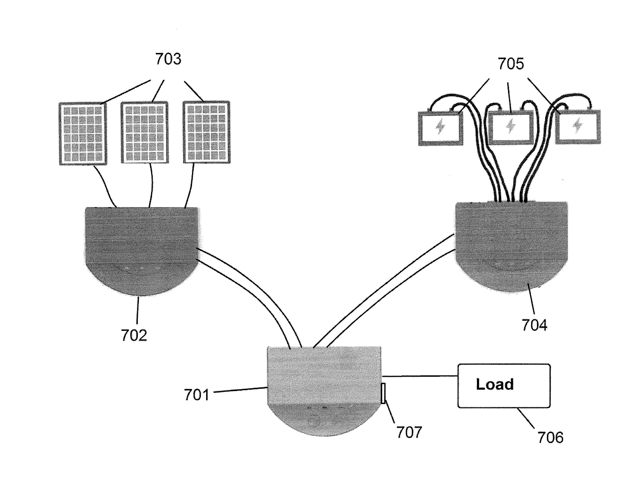
[0049]The present invention concerns novel lighting and charging system that may be used in areas that have an unreliable or absent electrical power grid. The system may include inter alia one or more electric power generation devices or “power devices” (e.g., solar panels, thermoelectri...


PUM


Abstract

The present invention includes self-contained, rechargeable power systems for areas having unreliable electrical grids or no electrical grid at all, and methods related thereto. The system may include one or more solar panels of various sizes to provide an off-grid power generation source, battery receivers for receiving batteries of various chemistries, and a control circuitry that is operable to detect the voltage and / or current output of the batteries that are installed in the system to determine their specific battery chemistry and then adjust the charge algorithm of the batteries to optimize both the charge capacity and the cycle life of the batteries. The control circuitry may also be operable to switch configurations of the solar panels and / or the batteries to optimize performance of the system. The system may be operable to power one or more light emitters and / or external electronic devices connected through the system by a charge port.

Description

FIELD OF THE INVENTION[0001]The present invention relates to a charging and lighting station, and more particularly to a solar power / recharging station for powering lights and external electronic devices, and recharging batteries and rechargeable devices, and methods of using and operating the same.BACKGROUND OF THE INVENTION[0002]Devices that utilize rechargeable batteries and solar panels for charging the batteries are useful in underdeveloped and developing countries and in remote areas where there is no reliable electric power grid system available. Alternative power sources for lighting, powering, and recharging devices are needed more than ever because of the modern proliferation and reliance upon electronic devices for communication.[0003]Such systems typically have set, inflexible designs that include only a specific solar panel or set of solar panels and a specifically designed battery or a specific type of battery. The designers of such systems often constrain the design, ...

Claims


Application Information

Patent Timeline
Patent Type & Authority Applications(United States)
IPC IPC(8): H02J1/00H02J7/35H05B33/08H02J7/00H05B44/00H05B45/50
CPCH05B33/0842H05B33/0815H02J7/0003H02J7/0021H05B33/0884H02J7/35H02J1/00H05B33/0845H02J7/0024F21S6/003F21S9/02F21Y2115/10H05B45/10H05B45/375H05B45/325H05B45/50H05B45/56H02J7/00032H05B45/00H05B45/37
Inventor ELLENBERGER, JOHN C.
Owner ELEVATE TECH CORP
Why Eureka
Try Eureka