Device for creating a void space in a living tissue, the device including a handle with a control knob that can be set regardless of the orientation of the handle

a technology of living tissue and void space, which is applied in the field of devices for creating void spaces in living tissues, can solve the problems of increasing the cost of providing the device, difficult to set this type of curette, and inability to easily set the extended state position of the drive rod in the internal components

Active Publication Date: 2016-08-11
STRYKER CORP
View PDF16 Cites 56 Cited by
  • Summary
  • Abstract
  • Description
  • Claims
  • Application Information

AI Technical Summary

Benefits of technology

[0012]This invention relates to a new and useful medical / surgical device. The medical / surgical device of this invention includes a handle designed to be held by the practitioner in a single hand. An elongated member extends forward from the handle. A working tip is located at the distal end of the elongated member. Internal to the handle is a mechanism for regulating the actuation of the working tip. A knob is rotatably mounted to the handle so the practitioner can regulate the actuation of the working tip. The knob is rotatably mounted to the handle so that regardless of the orientation and position of the handle relative to the practitioner using the device, the practitioner can, with the thumb or fingers of the hand holding the handle set the knob.
[0014]One version of this invention is a new and useful cavity creator for creating cavity in the tissue, such as bone, of a living being. The cavity creator of this invention includes an access cannula and a curette. The curette is constructed so that, through a wide range of orientations and positions of the cavity creator relative to the practitioner, the practitioner with minimal concentration and effort can manipulate the curette to set both the extent to which the tip extends from the access cannula and the orientation of the tip.
[0017]The above features of the curette of the void creator of this invention make it relatively easy to, with a single hand and throughout a wide range of curette orientations relative to the practitioner holding the curette, both rotate the handle and rotate the knob. This makes it relatively easy to, when the cavity creator is in different orientations, both set the extent to which the tip is extended from the access cannula and the orientation of the tip relative to an axis through the access cannula.

Problems solved by technology

A disadvantage of a number of these curettes is that their internal components do not allow one to easily set the extended state position of their drive rods.
This means that, in turn, it is difficult to set this type of curettes so as to with a degree of precision, control the extent to which the tip extends beyond the complementary access cannula.
As with any device, the more parts required to build the device increases the cost of providing the device.
This causes the connector to return to its unconstrained, bent, state.
Having to take this extra step adds to the ergonomic complexity of using this type of curette.
The increasing length of the handle of this curette can make it difficult to position the curette around the fluoroscope.
Further, many curettes, regardless of the type of assemblies that pivot their tips, share a common problem.
When the cavity creator with which one of these curettes is integral is in certain positions, it is difficult for the practitioner to hold the handle so as to rotate the handle and / or set the extent to which the curette shaft is extended.
The presence of equipment, for example a fluoroscope, may make it difficult for the practitioner to simply reposition himself / herself adjacent the right side of the patient.
This puts the hand of the practitioner in an awkward position relative to the component of the curette he / she needs to manipulate.
This makes it difficult for the practitioner to set the curette to ensure that tip is properly positioned.
The control members associated with a number of these devices have share a disadvantage with the cavity creators.
It can be difficult to control the device depending on the orientation and position of the device relative to the practitioner.

Method used


Image

  • Device for creating a void space in a living tissue, the device including a handle with a control knob that can be set regardless of the orientation of the handle
  • Device for creating a void space in a living tissue, the device including a handle with a control knob that can be set regardless of the orientation of the handle
  • Device for creating a void space in a living tissue, the device including a handle with a control knob that can be set regardless of the orientation of the handle

Examples


Embodiment Construction

I. Cavity Creator with First Curette

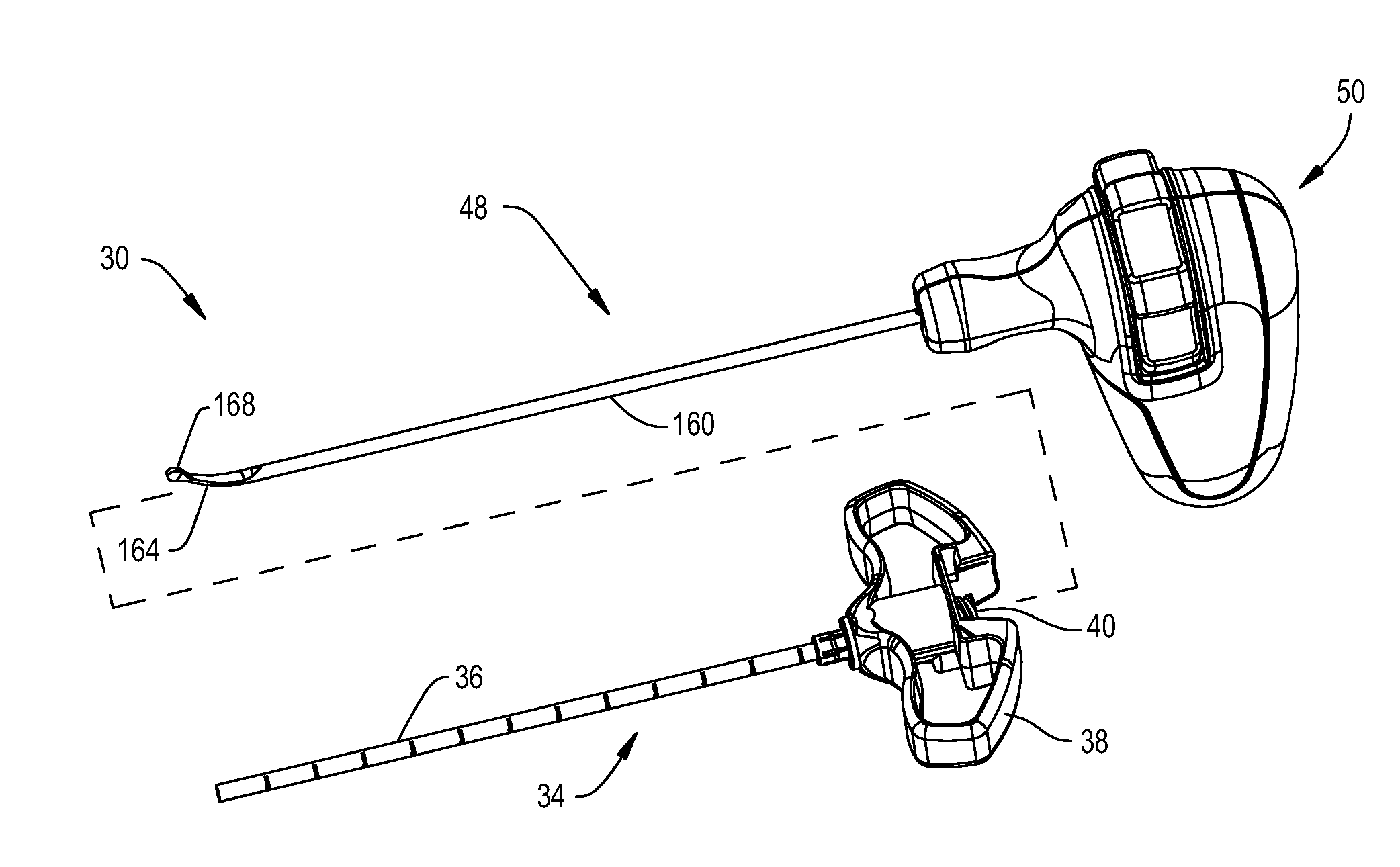
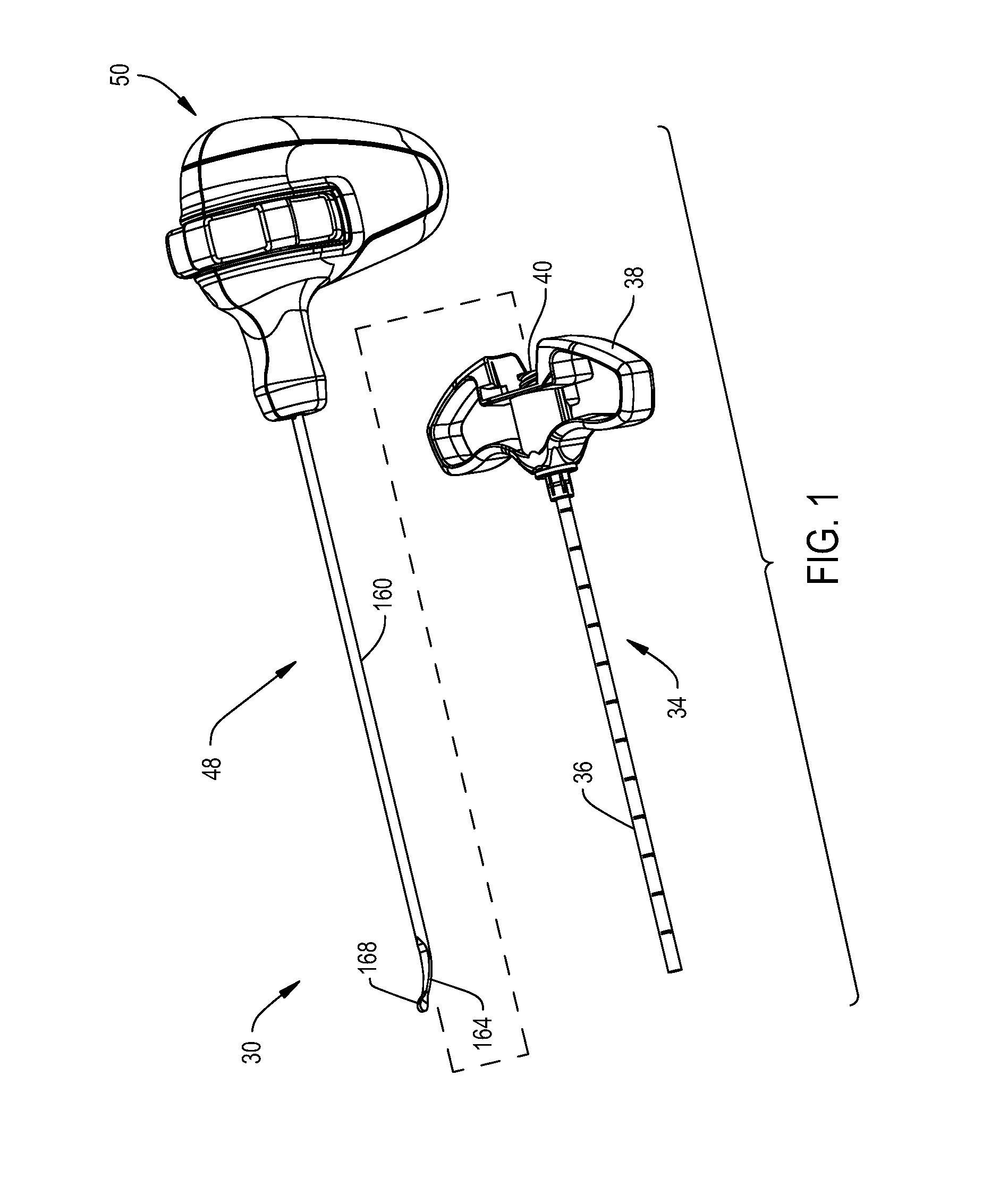
[0044]FIG. 1 depicts the components forming a cavity creator 30 of this invention. Specifically, cavity creator 30 includes an access cannula 34 and a curette 48. The access cannula 34 includes a tube 36 formed from material able to penetrate both soft tissue and hard tissue (bone). The distal end of tube 36 may have beveled edge to facilitate the insertion of the tube into the patient. (Here, “distal” is understood to mean away from the practitioner holding the cavity creator 30, towards the site to which the cavity creator is applied. “Proximal” is understood to mean towards the practitioner and away from the site to which the cavity creator 30 is applied.) A handle 38 is molded or otherwise secured over the proximal end of tube 36. The handle 38 is formed with a fitting 40 that opens into the lumen internal to tube 36. While not identified, the fitting is formed with threading. The threading facilitates the releasably coupling of either a cannu...


PUM


Abstract

A device for creating a void space in living tissue includes a handle from which a shaft extends. A tip is moveably attached to the distal end of the shaft. The angular position of the tip is controlled by the rotation of a knob mounted to the handle. The knob is mounted to the handle to project beyond opposed side surfaces of the handle and a surface that bridge between the side surfaces.

Description

FIELD OF THE INVENTION[0001]This invention relates generally to a device useful for creating a void space in living tissue such as bone. The device of this invention includes a handle with a control knob for regulating the setting of the device. The handle is constructed so that when the device is in different positions and positions and orientations relative to the practitioner using the device, the practitioner is able to easily hold the handle and set the knob.BACKGROUND OF THE INVENTION[0002]There are a number of medical devices used to create void spaces such as cavities or channels in living tissue such as bone. One such device is a cavity creator. A cavity creator is a surgical tool assembly that, as implied by its name, forms a cavity in the tissue of a living being. A number of cavity creators are specifically designed to form cavities in hard tissue, more specifically, bone. This type of cavity creator may be used in a procedure generally known as a vertebral augmentation ...

Claims


Application Information

Patent Timeline
Patent Type & Authority Applications(United States)
IPC IPC(8): A61B17/16
CPCA61B17/1617A61B17/162A61B17/1626A61B17/1631A61B17/1642A61B17/320708A61B17/1697A61B17/3472A61B2017/0046A61B2017/00867A61B17/1622A61B17/1671A61B2017/00389A61B2017/00424A61B2090/062
Inventor BROCKMAN, CHRISTOPHER SCOTTVANGEMERT, GEOFFREY JAMES
Owner STRYKER CORP
Why Eureka
Try Eureka