Method for recovering machining waste by input of energy and machining machine comprising a waste recovery system

a technology of machining machine and waste, which is applied in the direction of abrasive machine appurtenance, material removal/addition, climate sustainability, etc., can solve the problems of difficult surfaces, cap or bellows, and documents that cannot enable permanent contact with the surface, so as to facilitate suction and reduce waste

Active Publication Date: 2016-08-11
JEDO TECH
View PDF7 Cites 3 Cited by
  • Summary
  • Abstract
  • Description
  • Claims
  • Application Information

AI Technical Summary

Benefits of technology

[0017]Under the conditions of machining difficult surfaces, the method according to the invention adapts directly to the variation of distance (cutting depth) between the discharge head and the machined surface and optimizes the suction of the waste via this adaptation. This enables the functions of sealing, porosity and sweeping to be retained, regardless of this variable cutting depth, given that the machining quality—that is to say, the machined depth—is affected neither by the variation of the cutting depth nor by the inclination of the jet.

Problems solved by technology

The processed panels may have curves, in particular the panels of composite material which are used in the aeronautical industry, and thus form difficult surfaces.
However, the cap or bellows described in these documents do not enable permanent contact to be maintained with the surface to be processed, in particular when this surface is difficult, when a movement in two axes is carried out: the “sealing” with this surface is not ensured and the air originating from the outer side can pass between these connection means of the prior art and the surface.
In addition to the sealing, these connection means do not ensure the confinement of the waste which may be discharged outside the boundaries during the movement of the movable discharge head: the means of the prior art do not define porosity which is capable of preventing waste from being discharged whilst allowing suction air to enter.
Furthermore, the means of the prior art do not carry out a reliable sweeping operation of the machined surfaces since, during the movement of the discharge head, waste which is not drawn in does not always remain confined in the machining surface as a result of the lack of sealing and porosity.

Method used


Image

  • Method for recovering machining waste by input of energy and   machining machine comprising a waste recovery system
  • Method for recovering machining waste by input of energy and   machining machine comprising a waste recovery system
  • Method for recovering machining waste by input of energy and   machining machine comprising a waste recovery system

Examples


Embodiment Construction

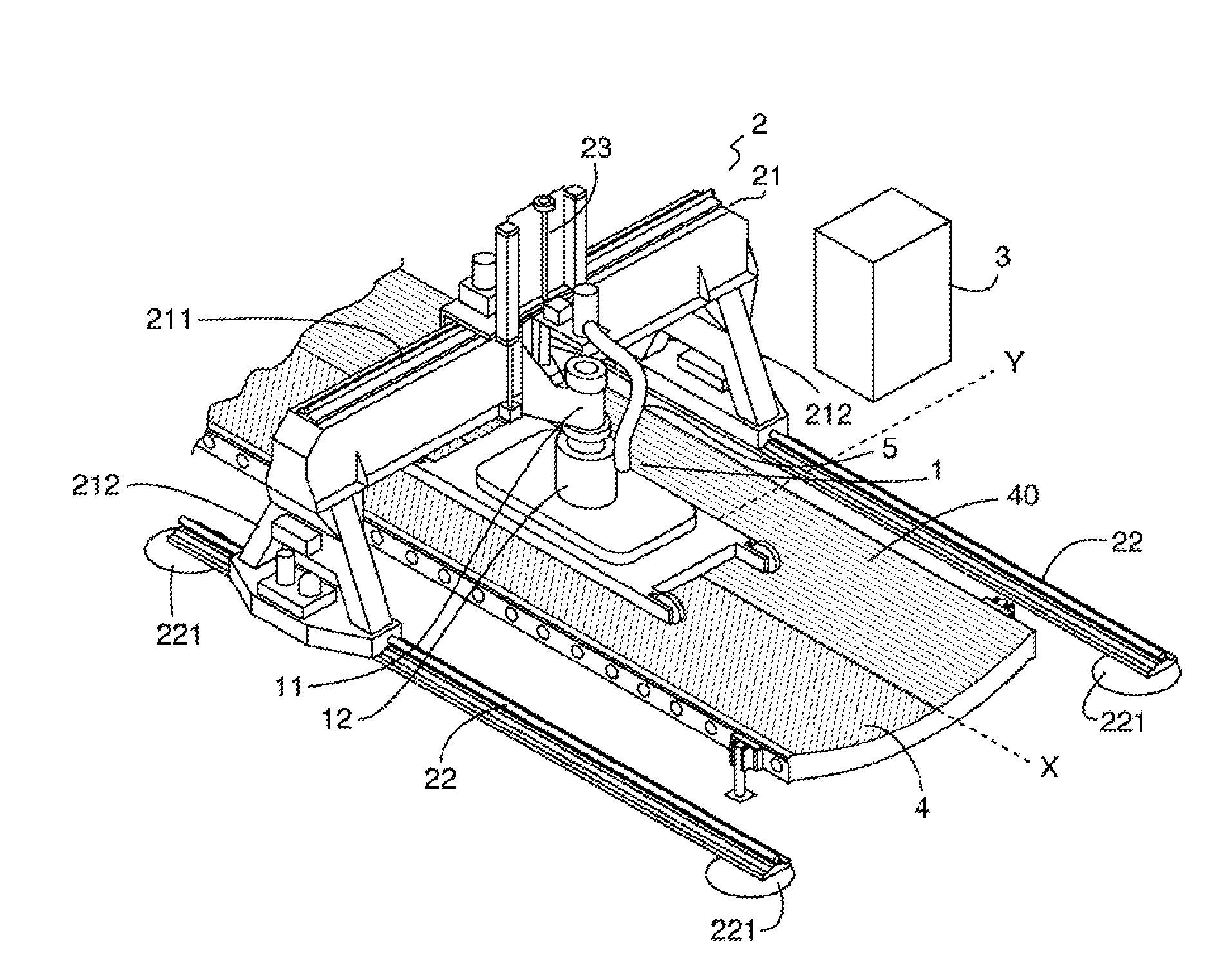
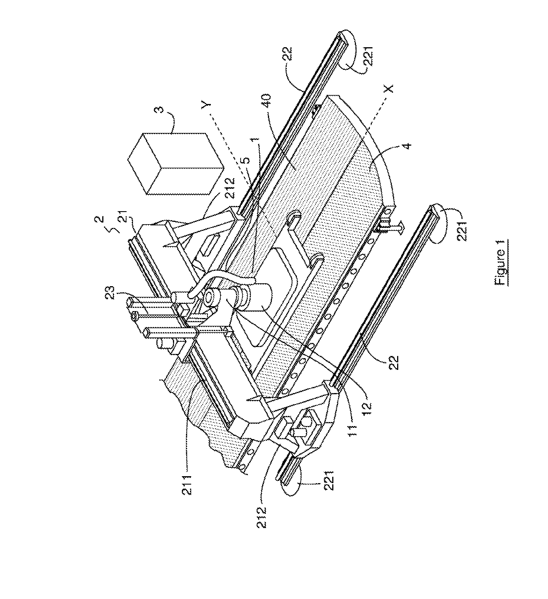
[0045]With reference to the general schematic view of FIG. 1, an example of a portable machining machine 1 using a pressurized jet according to the invention is driven by a guiding system 2 having two axes X, Y with numerical control 3, in order to machine a curved surface 4, an aircraft fuselage portion of composite material in the example illustrated.

[0046]The guiding system 2 comprises a gantry 21 which is composed of a transverse beam 211 which is supported at the end by feet 212 which move in translation -perpendicularly to the beam 211—on sliding members 22 via rollers (not illustrated), the sliding members 22 being maintained via suction pads 221 which are applied to the surface 4. The machine 1 is fixed via the discharge head 11 thereof to a chassis 23 which is capable of moving on the beam 211 via bearings (not illustrated).

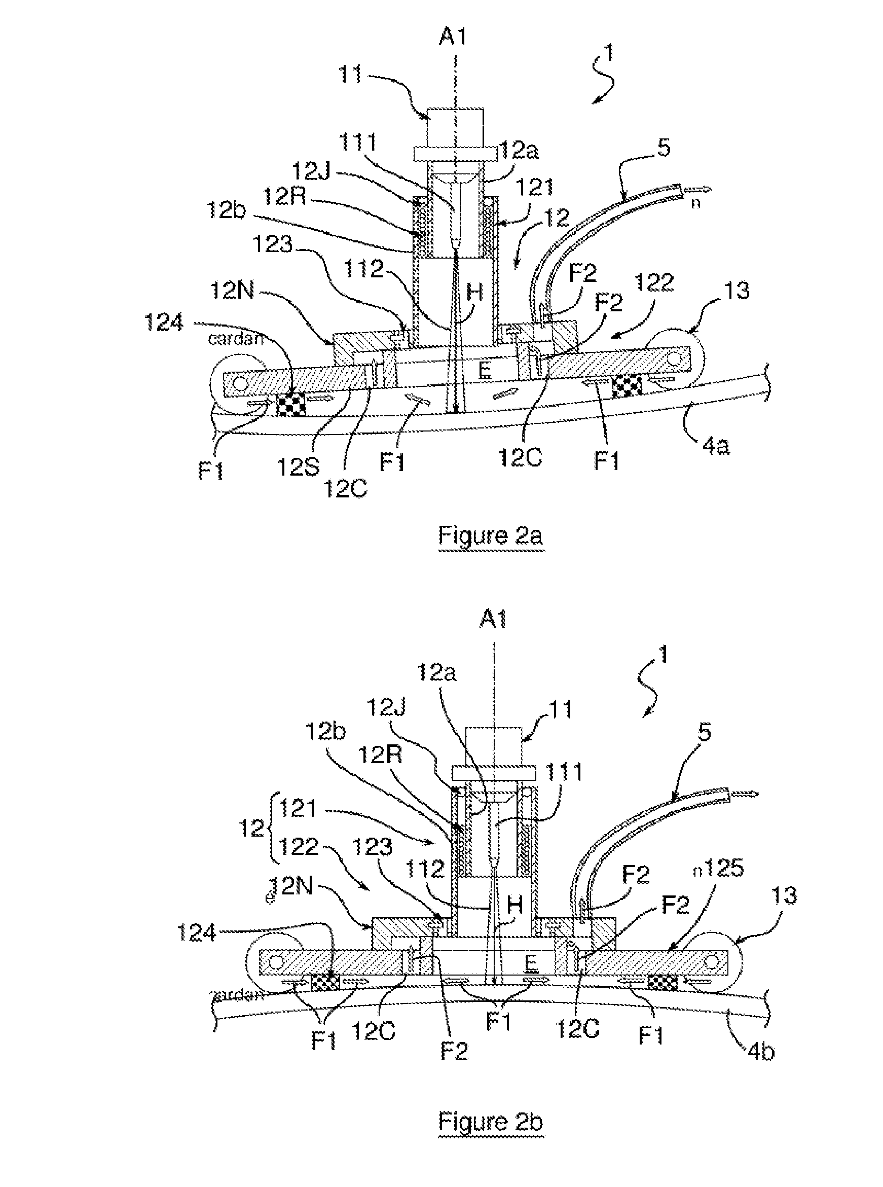
[0047]The discharge head 11 is extended by a chamber 12 which extends as far as the machined surface 4. This chamber 12 is connected to a suction pipe 5...


PUM


Abstract

The invention relates to implement the sealing, porosity and sweeping functions, combined. For this purpose, the present invention proposes to confine the waste and to suction the waste at the ejection head by means of a sufficiently flexible connection, such as to remain in contact with the machining area. According to an embodiment, a portable machining machine (1) operated by a pressurized jet (112) includes a waste recovery system (5), an injection head (11) which is provided with a nozzle (111) having an axis (A1) that is substantially perpendicular to the surface to be machined (4a) and which is driven by a digitally controlled two-axle guide system, the ejection head (11) being extended by an enclosure (12) to the surface area to be machined (4a). In addition, the enclosure (12) comprises a tubular portion (121) consisting of two walls (12a, 12b) which slide coaxially along the axis (A1) and a double-pivot articulation device (123). The enclosure (12) has a porous annular wall (124) in a plane substantially perpendicular to the axis (A1) of the nozzle (111), said annular wall (124) having sufficient resilience to keep the enclosure (12) in permanent sealing contact with the surface to be machined (4; 4a, 4b).

Description

CROSS REFERENCE TO RELATED APPLICATION[0001]This application is a national stage entry of PCT / ep2014 / 070036 filed September 19, 2014, under the International Convention claiming priority over French Patent Application No. 1359089 filed Sep. 20, 2013.TECHNICAL FIELD[0002]The invention relates to a method for recovering waste generated during machining by means of energy input and a machining machine using energy input provided with a waste recovery system which is capable of carrying out the method.BACKGROUND OF THE INVENTION[0003]Surface machining can be carried out by means of shot-blasting, using a cutting tool, by a chemical action or any method for emission of solid particles (sand, salt, etcetera) and / or fluid particles (in particular water). More particularly, the machining of large panel surfaces can be carried out using two types of system: a shaping tool, used by following the processed surface, or an energy input system, used without the need to follow the processed surfac...

Claims


Application Information

Patent Timeline
Patent Type & Authority Applications(United States)
IPC IPC(8): B24C3/06B24C9/00
CPCB24C3/065Y02P70/177B24C9/003Y02P70/10
Inventor DELERIS, MICHELCENAC, FRANÇOISBENEZECH, PASCAL
Owner JEDO TECH
Why Eureka
Try Eureka