Cord guide device and sewing machine provided with same

a technology of guide device and guide cord, which is applied in the direction of embroidering machine, automatic machine, textiles and paper, etc., can solve the problems of disadvantageous complexity and cost of sewing machine, and achieve the effect of reliably guiding the cord, reducing the rise of cloth, and simple and compact structur

Active Publication Date: 2016-08-11
JANOME CORP
View PDF15 Cites 3 Cited by
  • Summary
  • Abstract
  • Description
  • Claims
  • Application Information

AI Technical Summary

Benefits of technology

[0014]In the cord guide device of the present disclosure, since the disc-shaped cord guide that is provided with a guide hole that is positioned eccentrically with respect to the needle hole at the center is held in a rotatable manner about the needle hole with the guide support board and the pressing holder and is rotated in accordance with the movement of the cloth by the rotation mechanism, when sewing the cord or the like onto the cloth, the cord guide can be rotated in accordance with the movement of the cloth and the guide hole can always be positioned in the sewing direction (a direction opposite to the moving direction of the cloth) such that the cord or the like can be guided to the sewing position without the cord or the like being deviated from the needle location point.
[0015]Furthermore, since the cord guide and the guide support board have disc shapes with the needle hole at the center, the cord guide and the guide support board functions as a cloth presser that suppresses the cloth from rising caused by rising of the sewing needle; accordingly, a complicated cloth presser mechanism is not separately required.
[0016]While the cord guide device of the present disclosure has a simple and compact structure as described above, the cord guide device is capable of reliably guiding the cord or the like to the sewing position, is a device that facilitates mounting and dismounting thereof, and is a device that can be easily used.
[0017]Furthermore, in the exemplary embodiment in which the rotation mechanism includes the rotating body that comes into contact with the cloth and that is attached to the rotating shaft, which is attached to the guide arm extending from the underside of the cord guide and which serves as an axis of symmetry, and in which the rotating shaft is disposed orthogonally to the line connecting the center of the guide hole and the center of the needle hole and is attached to the guide arm at a position that is on the opposite side of the guide hole with respect to the needle hole and that is eccentric by a predetermined distance from the needle hole, the cord guide can be rotated by manually moving the cloth; accordingly, embroidery sewing using the cord or the like can be performed without using a controller and a rotation device that are complicated and costly.
[0018]Furthermore, in the exemplary embodiment including the drive mechanism that rotates the cord guide so that the guide hole is, with respect to the needle hole, positioned in the direction opposite to the direction, detected by the angle sensor, in which the cloth has moved, since the force to rotate the cord guide is exerted by the drive mechanism, the movement of the cloth can be performed in a further swift manner.

Problems solved by technology

The guide mechanism 40 also needs a controller that controls the rotation of the guide mechanism 40 on the basis of embroidery data; accordingly, the sewing machine is disadvantageously complicated and costly.

Method used


Image

  • Cord guide device and sewing machine provided with same
  • Cord guide device and sewing machine provided with same
  • Cord guide device and sewing machine provided with same

Examples


first exemplary embodiment

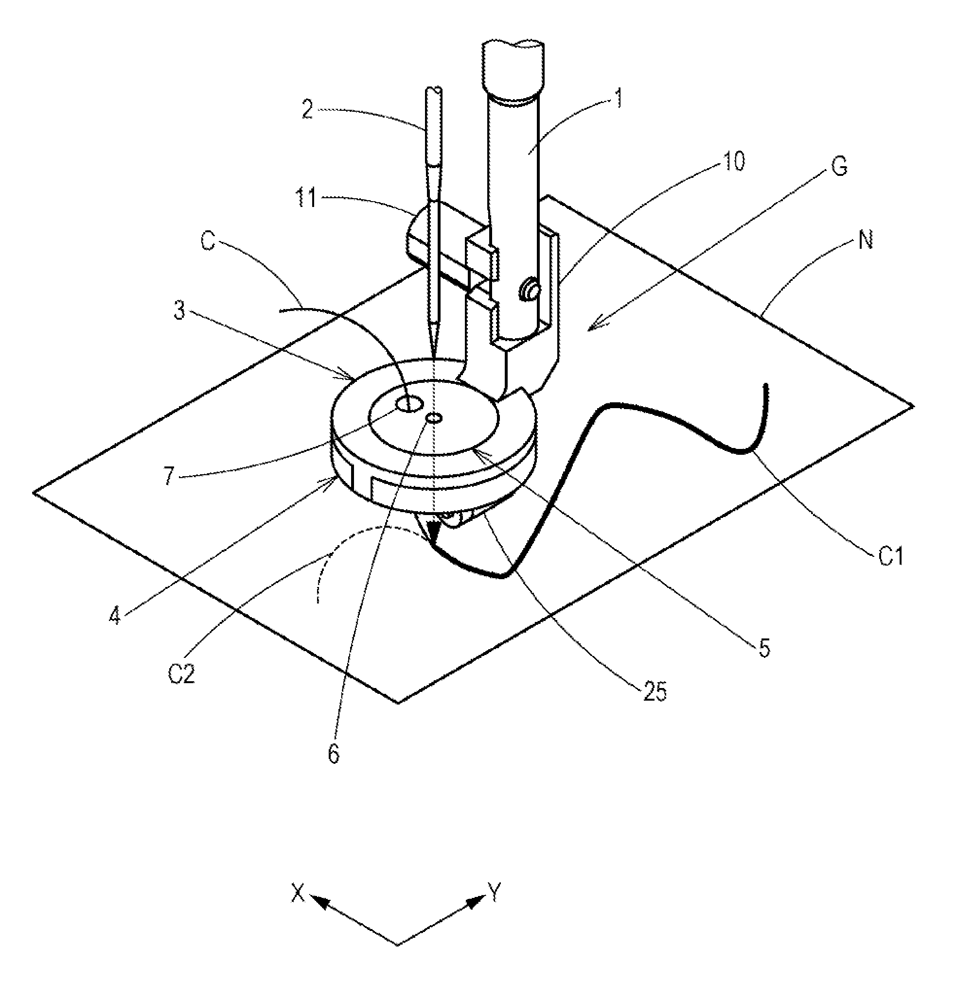
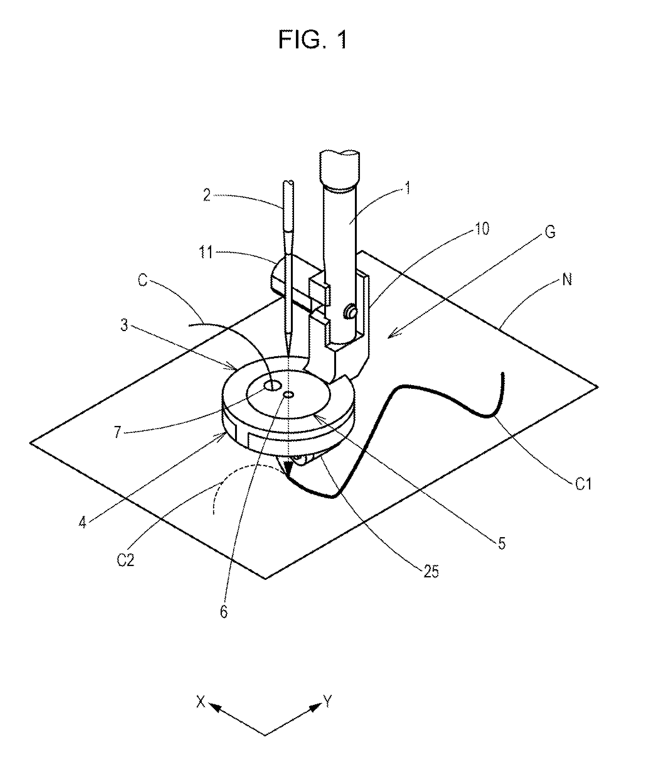
[0030]A guide attachment rod 1 illustrated in FIG. 1 is fixed to a sewing machine body (not shown) and is provided immediately behind a sewing needle 2 so as to hang therefrom when viewed from a sewer positioned on a front side of the sewing machine.

[0031]A cord guide device G is attached to a lower end of the guide attachment rod 1 through a holder arm 10 with a bolt 11.

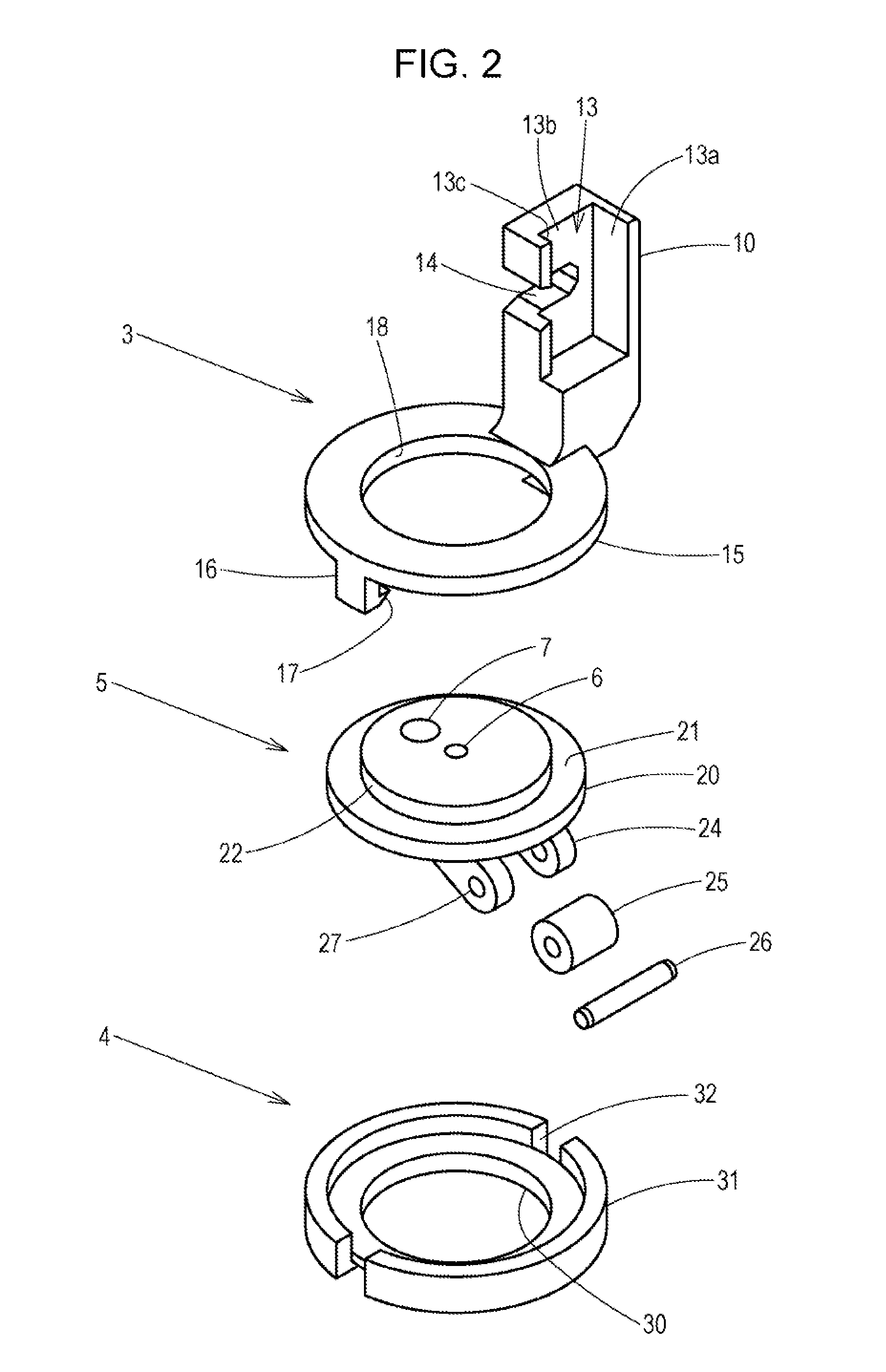
[0032]The cord guide device G includes a disc-shaped cord guide 5 that includes a needle hole 6 through which the sewing needle 2 is passed and a guide hole 7 through which a piece of cord C is passed, a guide support board 4 that supports an underside of the cord guide 5, and a pressing holder 3 that restricts an upper surface of the cord guide 5 and that is mounted on the guide attachment rod 1 with the holder arm 10.

[0033]A roller 25 described later is attached to a lower portion of the cord guide 5 so as to be in contact with a piece of cloth N.

[0034]Reference numeral N in FIG. 1 is a piece of cloth onto which a...

second exemplary embodiment

[0065]A second exemplary embodiment in which the cord guide is made rotatable by an operation lever and in which the connection mechanism of the pressing holder and the guide support board is changed will be described next.

[0066]Hereinafter, components that are the same as the first exemplary embodiment will be designated with the same reference numerals and points that are different will be described mainly.

[0067]As illustrated in FIGS. 7A to 8C, the cord guide 5 is equipped with an operation reception portion 43 that includes an insertion hole 44 into which an insertion piece 41 of an operation lever 40 can be fitted.

[0068]The operation reception portion 43 is provided on the underside of the base 20 so as to protrude therefrom and is provided on the outside of the guide arms 24 and inside an inner peripheral edge of the bottom plate 30 of the guide support board 4.

[0069]In the present exemplary embodiment, the insertion piece 41 is a flat tabular member and the insertion hole 44 ...

third exemplary embodiment

[0087]A third exemplary embodiment provided with, as a rotation mechanism, a drive mechanism that rotates the cord guide according to a moving direction of the cloth detected by an angle sensor will be described next.

[0088]Hereinafter, components that are the same as the first exemplary embodiment will be designated with the same reference numerals and points that are different will be described mainly.

[0089]As illustrated in FIGS. 9A and 9B, a driven gear 61 is provided on the outer peripheral edge of the base 20 of the cord guide 5. A drive mechanism 60 including a drive gear 62 that meshes with the driven gear 61 is accommodated inside a base 66 provided in the base portion of the holder arm 10 of the pressing holder 3.

[0090]A pulse motor 63 that rotates a shaft 64 on the basis of information from an angle sensor (not shown) is attached to the shaft 64 of the drive gear 62. The pulse motor 63 is mounted in the base 66 so as not to rotate.

[0091]In the present exemplary embodiment,...


PUM


Abstract

A cord guide device that is attached to a guide attachment rod of a sewing machine body, the cord guide device including a disc-shaped cord guide in which a needle hole through which a sewing needle passes is provided in a center and in which a guide hole through which a piece of cord or the like passes is provided, the guide hole being positioned eccentrically with respect to the needle hole; a guide support board that supports an underside of the cord guide; a pressing holder that, by being connected to the guide support board, restricts an upper surface of the cord guide and holds the cord guide such that the cord guide is rotatable about the needle hole; and a rotation mechanism that rotates the cord guide according to a movement of a piece of cloth.

Description

BACKGROUND OF THE INVENTION[0001]1. Field of the Invention[0002]The present disclosure is related to a cord guide device that guides an embroidery material such as a piece of cord when carrying out embroidery sewing with a sewing machine, and, in particular, relates to a cord guide device that guides a piece of cord or the like to a sewing position so that the cord or the like does not deviate from a needle location point when sewing the cord or the like onto a piece of cloth and to a sewing machine provided with the cord guide device.[0003]2. Description of the Related Art[0004]In embroidery sewing, there is a method of sewing a piece of cord or the like that is a string-like embroidery material, such as a piece of cord or tape, onto a piece of cloth.[0005]In order to sew a piece of cord or the like on a piece of cloth using a sewing machine by lock stitching that includes a needle thread and a bobbin thread, the cord or the like needs to be reliably guided to the needle location p...

Claims


Application Information

Patent Timeline
Patent Type & Authority Applications(United States)
IPC IPC(8): D05C7/08D05C5/00
CPCD05C7/08D05D2303/08D05C5/00D05B29/10
Inventor NAKAJIMA, MAKOTO
Owner JANOME CORP
Why Eureka
Try Eureka