Compliance voltage detector circuit

Active Publication Date: 2016-08-11
CIRTEC MEDICAL CORP
View PDF2 Cites 0 Cited by
  • Summary
  • Abstract
  • Description
  • Claims
  • Application Information

AI Technical Summary

Benefits of technology

The apparatus and method described in this patent text can monitor electrode drive voltages and detect if there is a coincidence in time between the voltage at different electrodes. This can be useful in detecting abnormal situations and ensuring safe operation.

Problems solved by technology

Implanted tissue stimulators are typically replaced periodically due to actual or expected battery failure.

Method used


Image

  • Compliance voltage detector circuit
  • Compliance voltage detector circuit
  • Compliance voltage detector circuit

Examples


Embodiment Construction

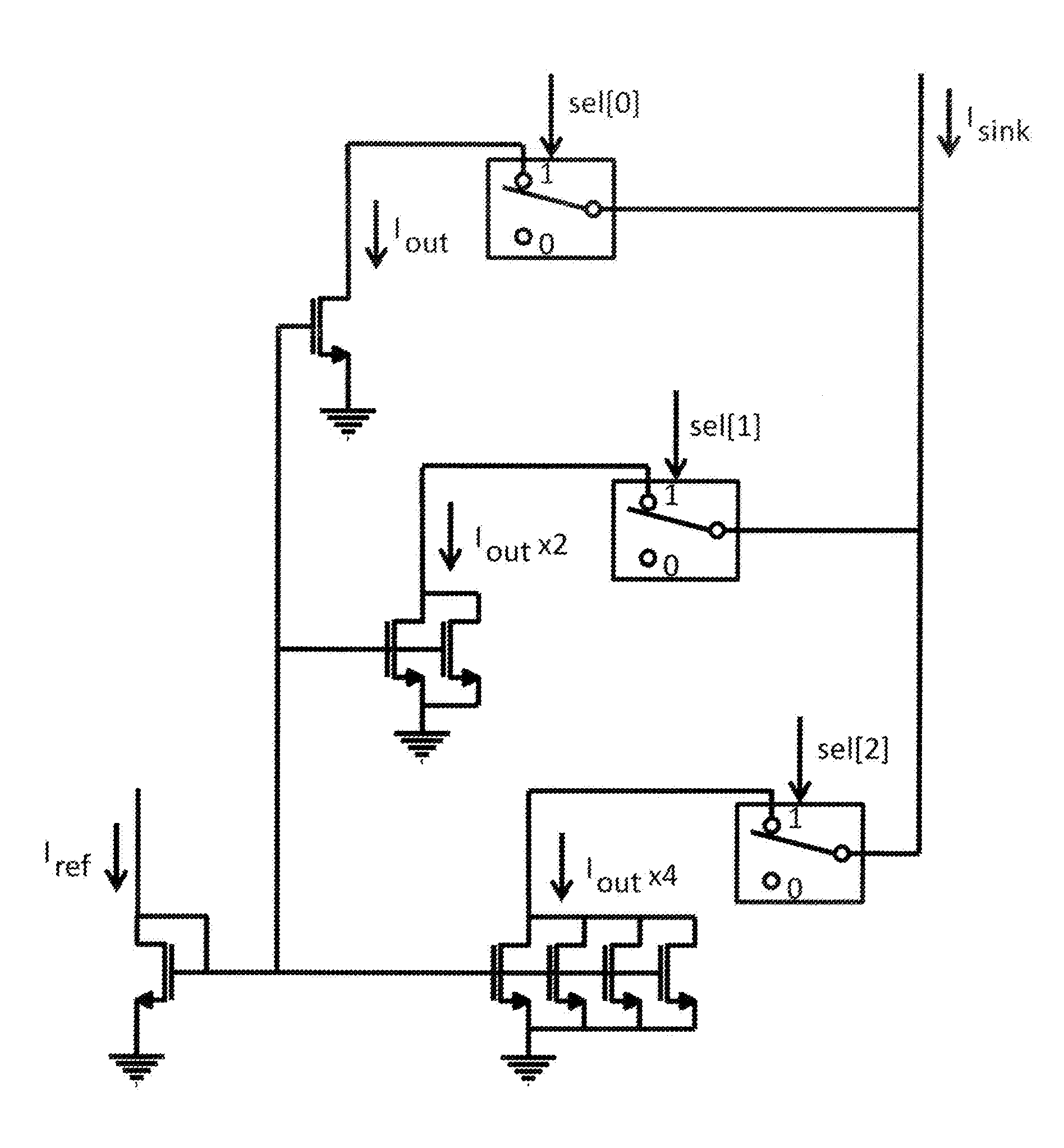
[0030]Methods, apparatus, and circuitry as described herein may be used, for example, to monitor and adjust a compliance voltage in an implantable stimulator device. Such principles may be used, for example, to obtain an implantable medical device (e.g., a neurostimulator or other tissue stimulator) with a compliance voltage detector to adjust the voltage used by an output current source / sink circuit to ensure proper circuit performance while limiting power use.

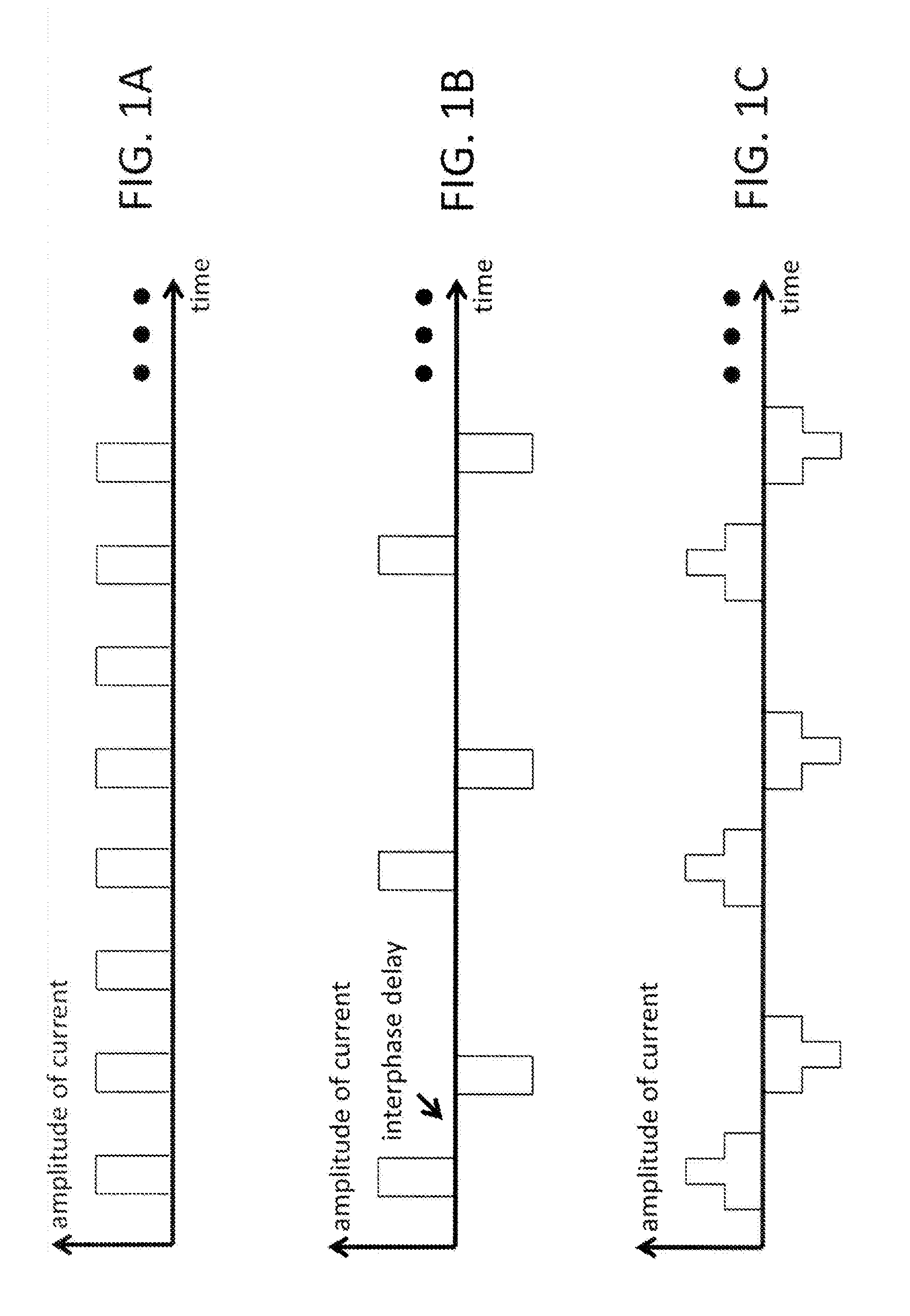
[0031]A tissue stimulator may operate by delivering a desired amount of charge to a region of tissue into which electrodes have been implanted. FIG. 1A shows an example of a monophasic mode of operation, in which charge is delivered in a series of pulses of the same polarity. FIG. 1B shows an example of a biphasic mode of operation, which is more common. In biphasic operation, charge is delivered and removed in each pair of a series of pairs of pulses of opposite polarity, where the delivery and removal pulses in each pair ar...


PUM


Abstract

A system, method, and circuit to monitor a compliance voltage in an implantable stimulator device. An implantable medical device with a compliance voltage detector to monitor the voltage used by an output current source / sink circuit to ensure proper circuit performance while limiting power use.

Description

RELATED APPLICATION[0001]This application claims priority to U.S. Provisional Application No. 62 / 113,312, entitled “Compliance Voltage Detector Circuit” filed Feb. 6, 2015 and is hereby incorporated by reference in its entirety.BACKGROUND[0002]1. Field of the Disclosure[0003]Aspects of the disclosure relate in general to tissue stimulation by an implantable device.[0004]2. Description of the Related Art[0005]Devices used to deliver electrical stimulation to body tissue (e.g., nerves and / or muscles) may be generally referred to as tissue stimulators. Particular examples of such devices for stimulating nerves and / or muscles include cardiac pacemakers, cardiac defibrillators, cochlear stimulators, spinal cord stimulators, retinal stimulators, and cortical stimulators. A tissue stimulator designed for implantation in the body may also be called an implanted pulse generator (IPG) and is typically battery-powered.[0006]A tissue stimulator designed to deliver electrical stimulation to the ...

Claims


Application Information

Patent Timeline
IPC IPC(8): G01R19/00G01R19/165
CPCG01R19/165G01R19/0084G01R19/16566
Inventor ILLEGEMS, PAUL F.
Owner CIRTEC MEDICAL CORP
Why Eureka
Try Eureka