
Light guide plate and LED lamp

a technology of led lamps and guide plates, which is applied in the direction of lighting and heating apparatus, semiconductor devices for light sources, instruments, etc., can solve the problems of low energy efficiency, high electricity consumption, and high heat generation, and achieve high production efficiency, simple manufacturing process, and improved safety and power use

Active Publication Date: 2016-08-18
THE DESIGN HOUSE LLC +1
View PDF23 Cites 2 Cited by
  • Summary
  • Abstract
  • Description
  • Claims
  • Application Information

AI Technical Summary

Benefits of technology

The patent text describes a method of making a light guide substrate by injection molding. This process is simple and can make the substrate and the diffuse reflection points at the same time. This makes it easy to produce and reduces costs.

Problems solved by technology

1, high heat is produced by electricity, high electricity is consumed, and the energy efficiency is low;
2, the tungsten lamp can only be made into a relatively high-voltage product, so the safety performance of the product is low;
3, the tungsten filaments are easily oxidized, so internal sealing is required; the toughness of the tungsten filaments is low, so the stability of the product is low;
4, a product with a filament of a complex shape, such as an Edison lamp, requires great care in manufacturing, so the production efficiency is low; and
5, the housing which can only be made of glass is fragile and poor in safety.
In the lamp, LED wafers are connected in series and in parallel with each other in such a way as to mimic the look of tungsten filaments.. Although theses lamps can provide the look of a conventional tungsten lamp, the cost is high.
Moreover, because many LED wafers are adopted, the voltage and the current are relatively high, and the safety performance of the product is low.

Method used


Image

  • Light guide plate and LED lamp
  • Light guide plate and LED lamp
  • Light guide plate and LED lamp

Examples


embodiment 1

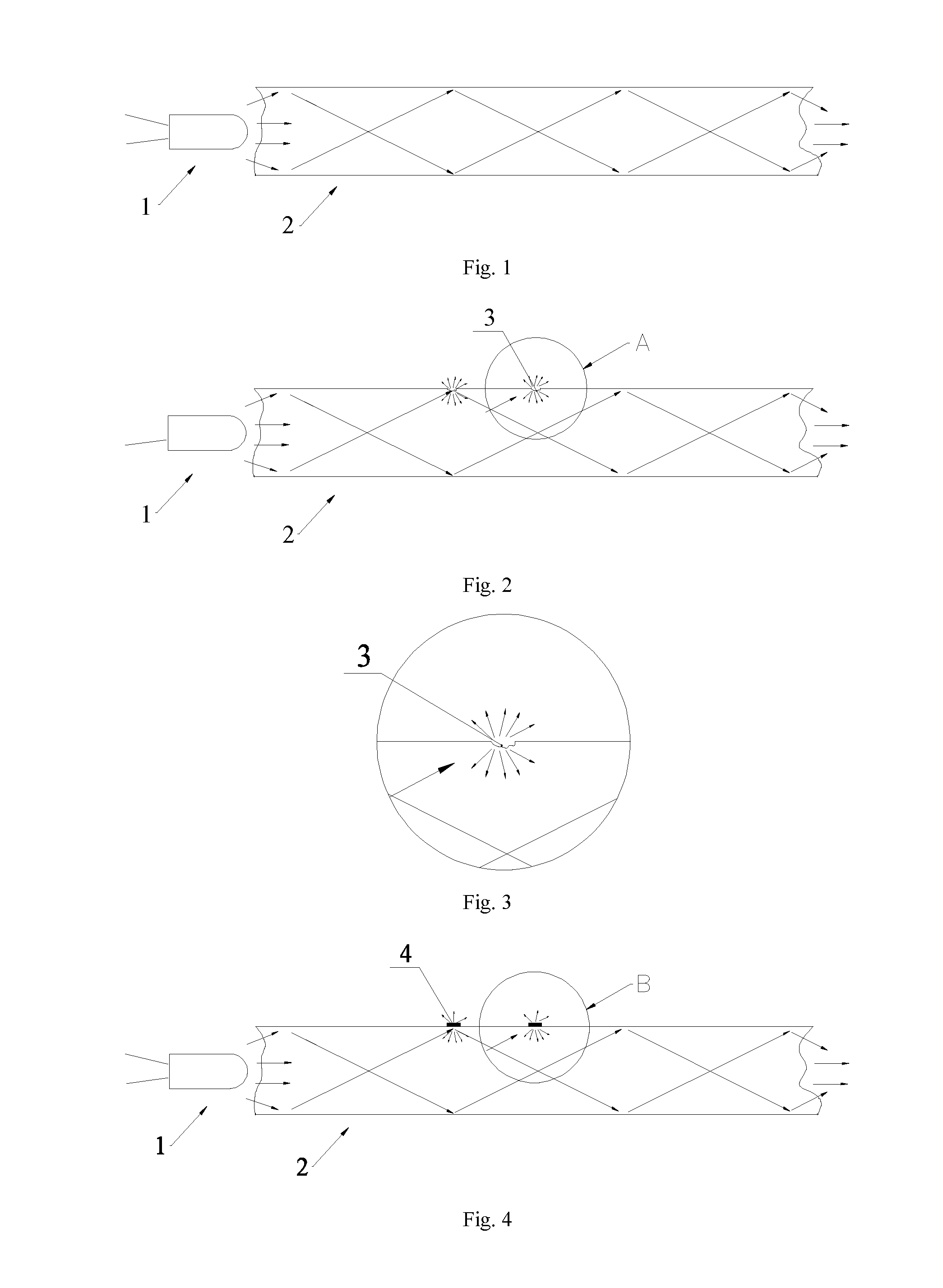
[0058]As shown in FIG. 1, light of a light source 1 is totally reflected after entering a light guide substrate 2, and the light finally penetrates through a side wall opposite to an incident side wall after being totally reflected multiple times.

[0059]As shown in FIG. 2 and FIG. 6, a light guide plate includes the light guide substrate 2, wherein the light guide substrate is provided with an incident side wall; and the light guide substrate is at least provided with a side wall intersecting the incident side wall, which has a plurality of continuous or discontinuous diffuse reflection points.

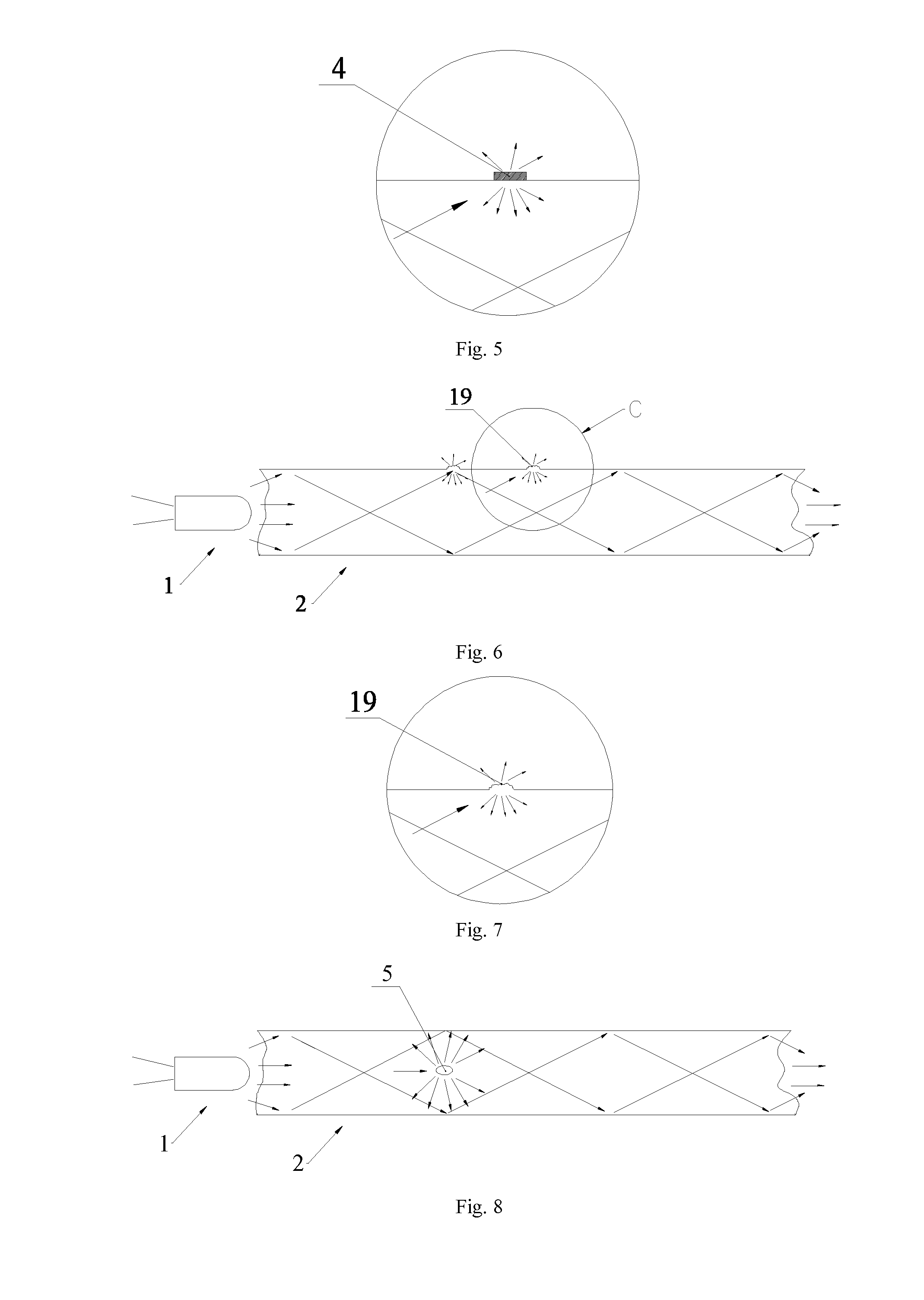
[0060]As shown in FIG. 2 and FIG. 6, light emitted by the light source 1 may penetrate through the concave points 3 or the convex points 19, i.e., the concave points or the convex points emit light.

[0061]As shown in FIG. 3, the diffuse reflection points may be concave points 3. As shown in FIG. 7, the diffuse reflection points may also be convex points 19. The design of the convex points or the...

embodiment 2

[0064]As shown in FIG. 4 and FIG. 5, the diffuse reflection points are crystal 4 or ink fixed on the side wall of the light guide substrate. The crystal 4 may be disposed onto the light guide substrate by processes such as screen printing and the like. The crystal in this embodiment may be titanium dioxide. Ink may be disposed onto the light guide substrate by processes such as photoetching and the like.

[0065]As shown in FIG. 4, light emitted by the light source 1 may penetrate through the crystal 4, i.e., the crystal 4 emits light.

embodiment 3

[0066]As shown in FIG. 8, a light guide plate differs from the light guide plates of embodiments 1 and 2 in that diffuse reflection points are not arranged on the side wall of the light guide substrate 2 but arranged in the light guide substrate, and the diffuse reflection points are particles 5 with a scattering function. The particles, the diffuse reflection points may also be formed by bubbles in the light guide substrate.

[0067]The direction of light entering the particles may be changed by the particles with the scattering function, so that the light exits from the side wall of the light guide substrate. The total reflection of light in the light guide plate is affected by the diffuse reflection points or the particles such that the light exits from the side wall of the light guide substrate after passing through the diffuse reflection points or the particles.

[0068]As shown in FIG. 8, light emitted by the light source 1 changes direction in the particles 5 and then penetrates th...


PUM


Abstract

The present invention discloses an LED lamp comprising a light guide plate. The lamp comprises a mounting seat, an LED lamp panel and at least one light guide substrate, wherein the light guide substrate is provided with an incident side wall corresponding to the LED light-emitting unit, and the light guide substrate is at least provided with a side wall intersecting the incident side wall, which has one or more continuous or discontinuous diffuse reflection points. Light exits from the light guide substrate through the diffuse reflection points or particles. The diffuse reflection points, and thus the pattern of emitted light, can form complex or decorative patterns, or can be random.

Description

FIELD OF THE INVENTION[0001]The present invention relates to the field of lamps for illumination or decorative illumination.BACKGROUND OF THE INVENTION[0002]A tungsten lamp is an incandescent lamp having filaments made of tungsten filaments, wherein the filaments are heated by electricity to an incandescent state and to emit visible electric light.[0003]The tungsten lamp has the following shortcomings:[0004]1, high heat is produced by electricity, high electricity is consumed, and the energy efficiency is low;[0005]2, the tungsten lamp can only be made into a relatively high-voltage product, so the safety performance of the product is low;[0006]3, the tungsten filaments are easily oxidized, so internal sealing is required; the toughness of the tungsten filaments is low, so the stability of the product is low;[0007]4, a product with a filament of a complex shape, such as an Edison lamp, requires great care in manufacturing, so the production efficiency is low; and[0008]5, the housing...

Claims


Application Information

Patent Timeline
Patent Type & Authority Applications(United States)
IPC IPC(8): F21V8/00F21Y115/10
CPCG02B6/0018F21Y2101/02G02B6/0075G02B6/0016G02B6/0036G02B6/0041G02B6/0043G02B6/006F21V3/00F21K9/61F21Y2115/10
Inventor LAN, PINGHAI
Owner THE DESIGN HOUSE LLC
Learn More