3D map display system

Inactive Publication Date: 2016-08-18
GEO TECHN LAB
View PDF4 Cites 2 Cited by
  • Summary
  • Abstract
  • Description
  • Claims
  • Application Information

AI Technical Summary

Benefits of technology

The present invention provides a method for generating an image of a character by parallel projection, which can be viewed from various angles without being obstructed by the perspective projection. The method allows for the creation of diversified and three-dimensional representations of characters without the need for large amounts of image data. The characters can be displayed in a way that avoids visibility issues and allows for easy recognition of the road surface while driving. The invention provides a more immersive and visually appealing display for the character representation.

Problems solved by technology

However, with a method of perspective projection of the plate polygon on which the characters are pasted, the characters subjected to the perspective projection can be hardly recognized visually if the plate polygon is arranged in parallel with a direction of the line of sight or if it is arranged far from the point of sight in some cases.
However, if a 3D map is to be displayed from various point of sights and direction of the line of sights by such method, various and diversified character images according to these point of sights and direction of the line of sights need to be prepared, and its data amount becomes huge.

Method used


Image

  • 3D map display system
  • 3D map display system
  • 3D map display system

Examples


embodiment 1

[0034]A. System configuration:

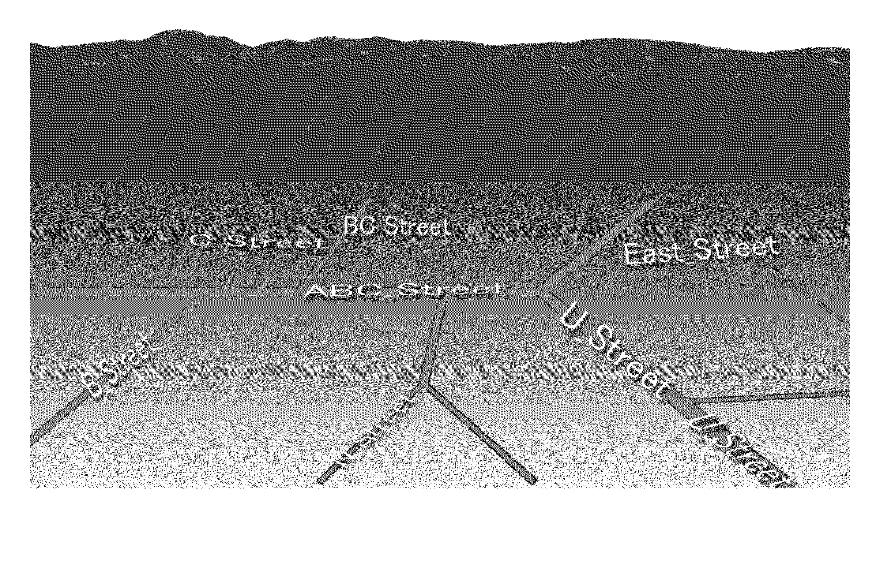
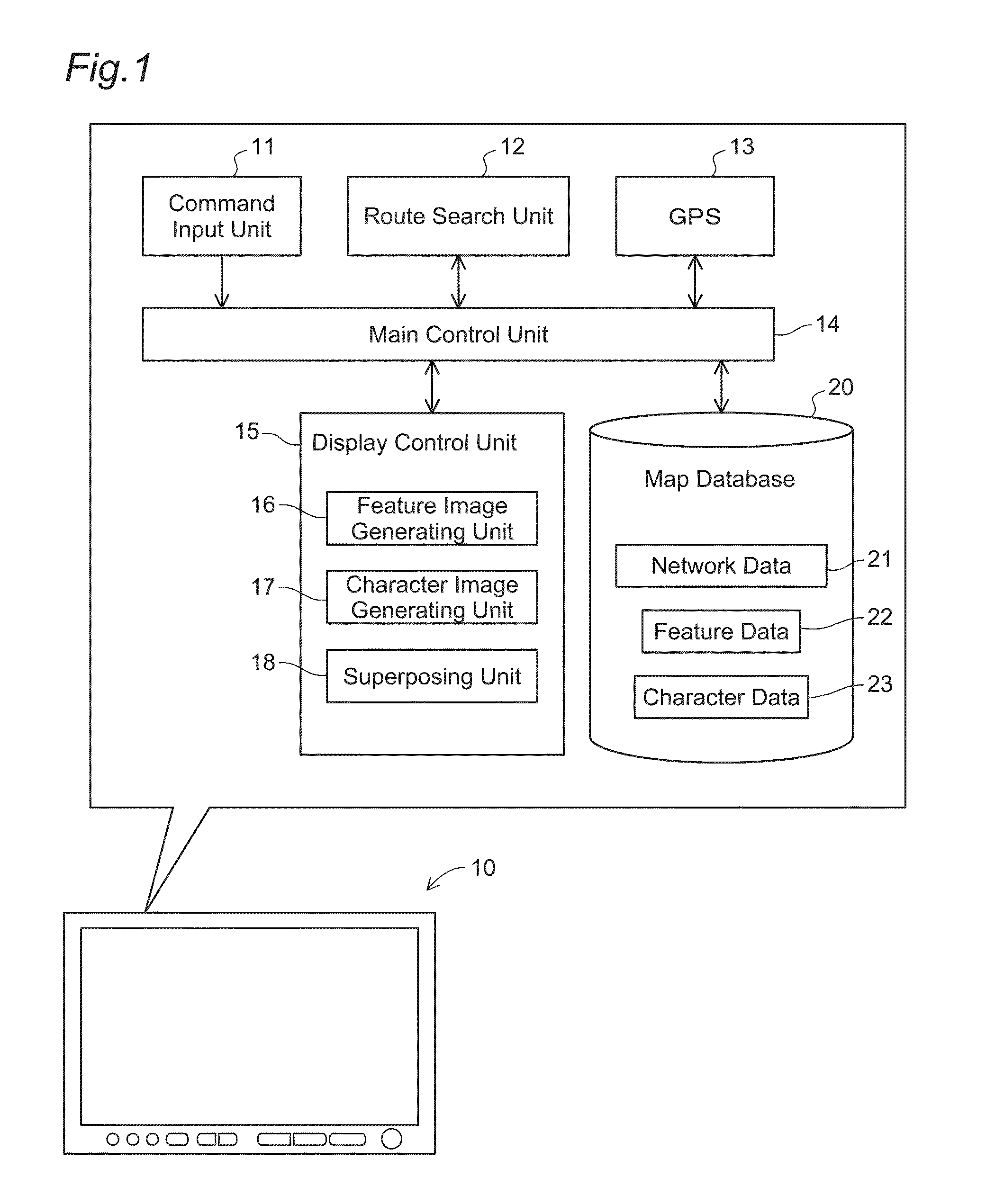
[0035]FIG. 1 is an explanatory view illustrating configuration of a 3D map display system 10. A configuration example as a navigation apparatus performing route guidance from a starting point to a destination specified by a user while displaying a 3D map is illustrated. In this embodiment, the present invention is not limited to the configuration as the navigation apparatus but also can be configured as a system only for displaying a map. Moreover, in this embodiment, a system operated in a stand-alone manner is exemplified but a part of functions illustrated in the figure may be configured by a plurality of servers and the like connected via a network.

[0036]The 3D map display system 10 is configured by a computer including a CPU, a RAM, and a ROM. Each illustrated functional block is configured by installing software for realizing these functions. The functions of each functional block are as follows.

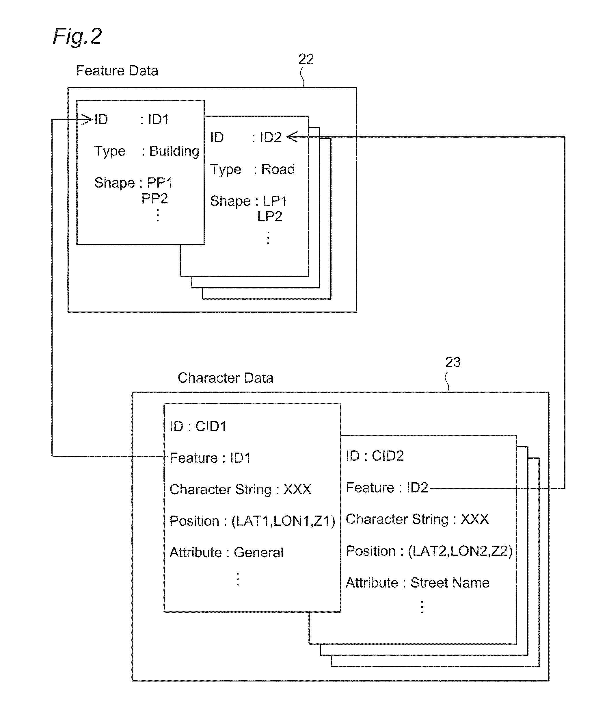
[0037]A map database 20 stores map data used for 3D ...


PUM


Abstract

In displaying a 3D map, a feature image is generated by perspective projection of the feature based on a predetermined position of the point of sight and a predetermined direction of the line of sight. A plate polygon on which characters are pasted is arranged in a virtual 3D space in a direction along a road and tilted from the ground surface, and parallel projection is applied to the plate polygon so as to generate a character image. A tilt angle between the plate polygon and the ground surface is set based on a display direction of the road and a display position of the character. Thus, by generating the feature image by perspective projection while generating the character image by parallel projection, negative effects such as crushing of distant characters can be avoided, whereby the characters can be displayed in three-dimensional shape without reducing visibility thereof.

Description

CLAIM OF PRIORITY[0001]This application is a Continuation of International Patent Application No. PCT / JP2015 / 052844, filed on Feb. 2, 2015, which claims priority to Japanese Patent Application No. 2014-055711, filed on Mar. 19, 2014, each of which is hereby incorporated by reference.BACKGROUND OF THE INVENTION[0002]1. Field of the Invention[0003]The present invention relates to a three-dimensional (3D) map display system which displays a 3D map three-dimensionally representing not only features but also characters.[0004]2. Description of the Related Art[0005]In an electronic map used for a navigation apparatus, a computer screen and the like, a 3D map three-dimensionally representing features such as a building is used in some cases. The 3D map is usually displayed by three-dimensionally drawing a 3D model by perspective projection or the like.[0006]In the 3D map, characters are also displayed in various aspects. Japanese Patent No. 3402011 illustrates an output example which draws ...

Claims


Application Information

Patent Timeline
IPC IPC(8): G06T15/20G06T11/60G06T17/05
CPCG06T17/05G06T15/20G06T11/60G01C21/00G01C21/3673G06T19/003G06T19/20G06T2219/2004
Inventor ARAMAKI, MASATOSHIKISHIKAWA, KIYONARITESHIMA, EIJIUCHINOUMI, MASASHINAKAGAMI, MASARUAZAKAMI, TATSUYAYONEKURA, TATSUROU
Owner GEO TECHN LAB
Why Eureka
Try Eureka