Shield Structure, Shield Shell, and Method for Manufacturing Shield Connector with Electric Wire
- Summary
- Abstract
- Description
- Claims
- Application Information
AI Technical Summary
Benefits of technology
Problems solved by technology
Method used
Image

Examples
first embodiment
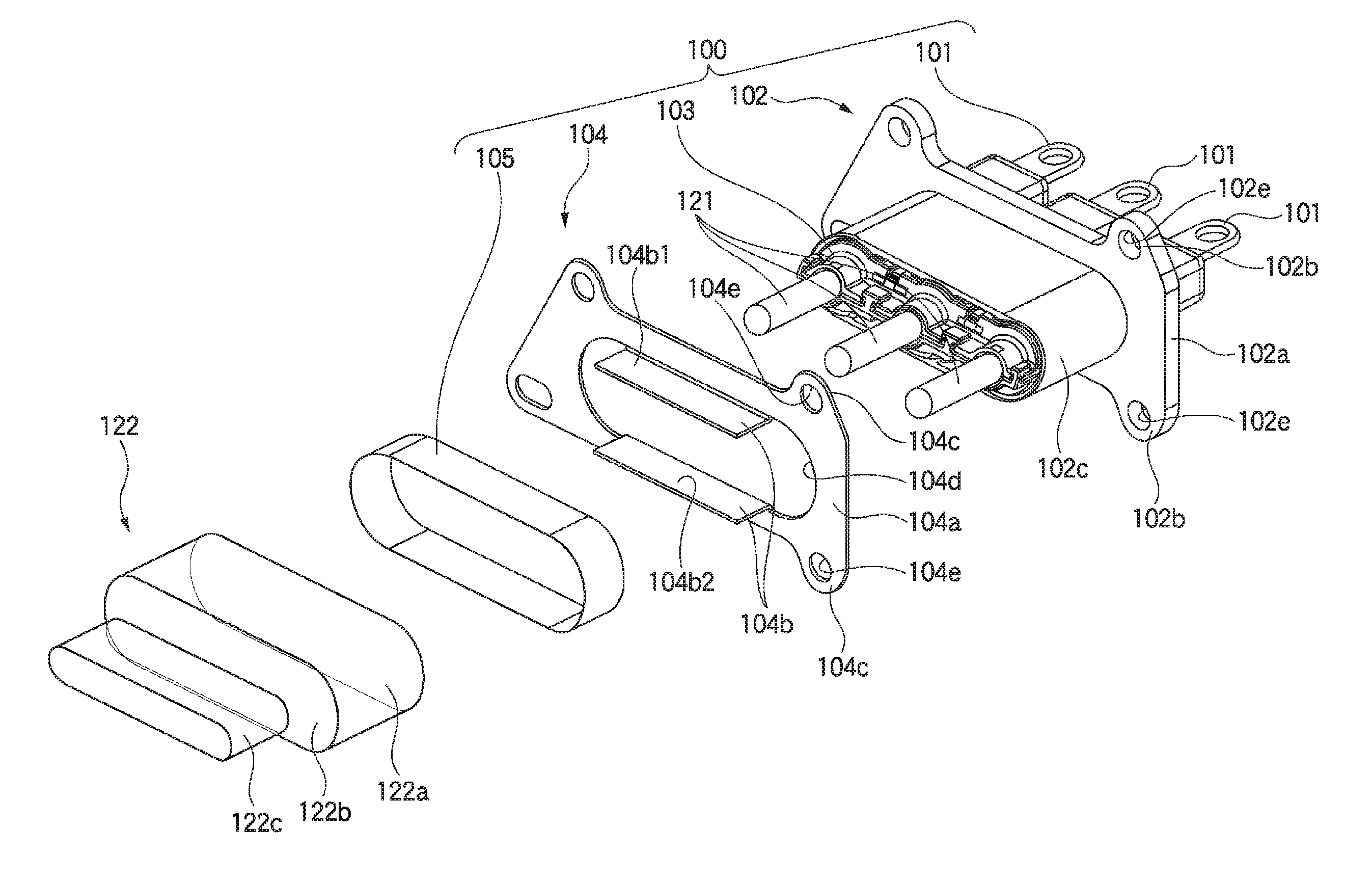
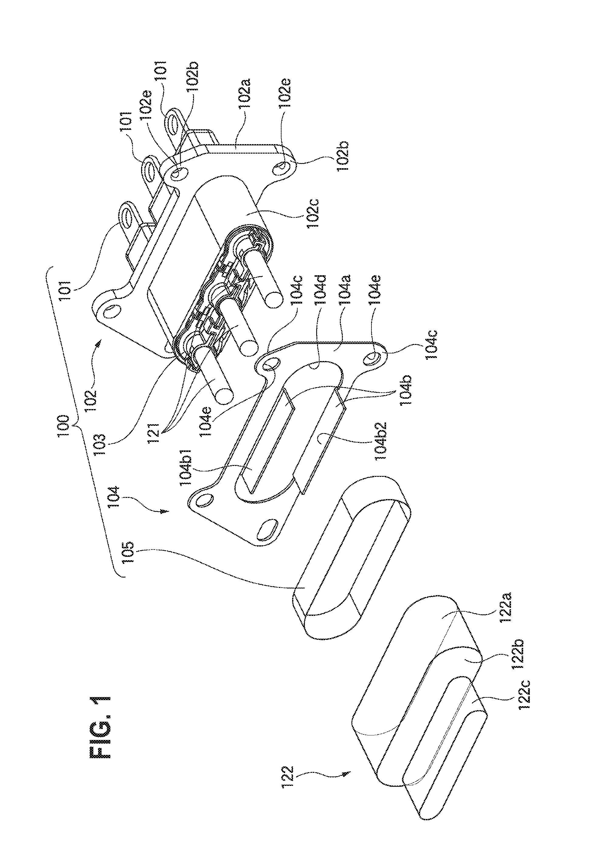
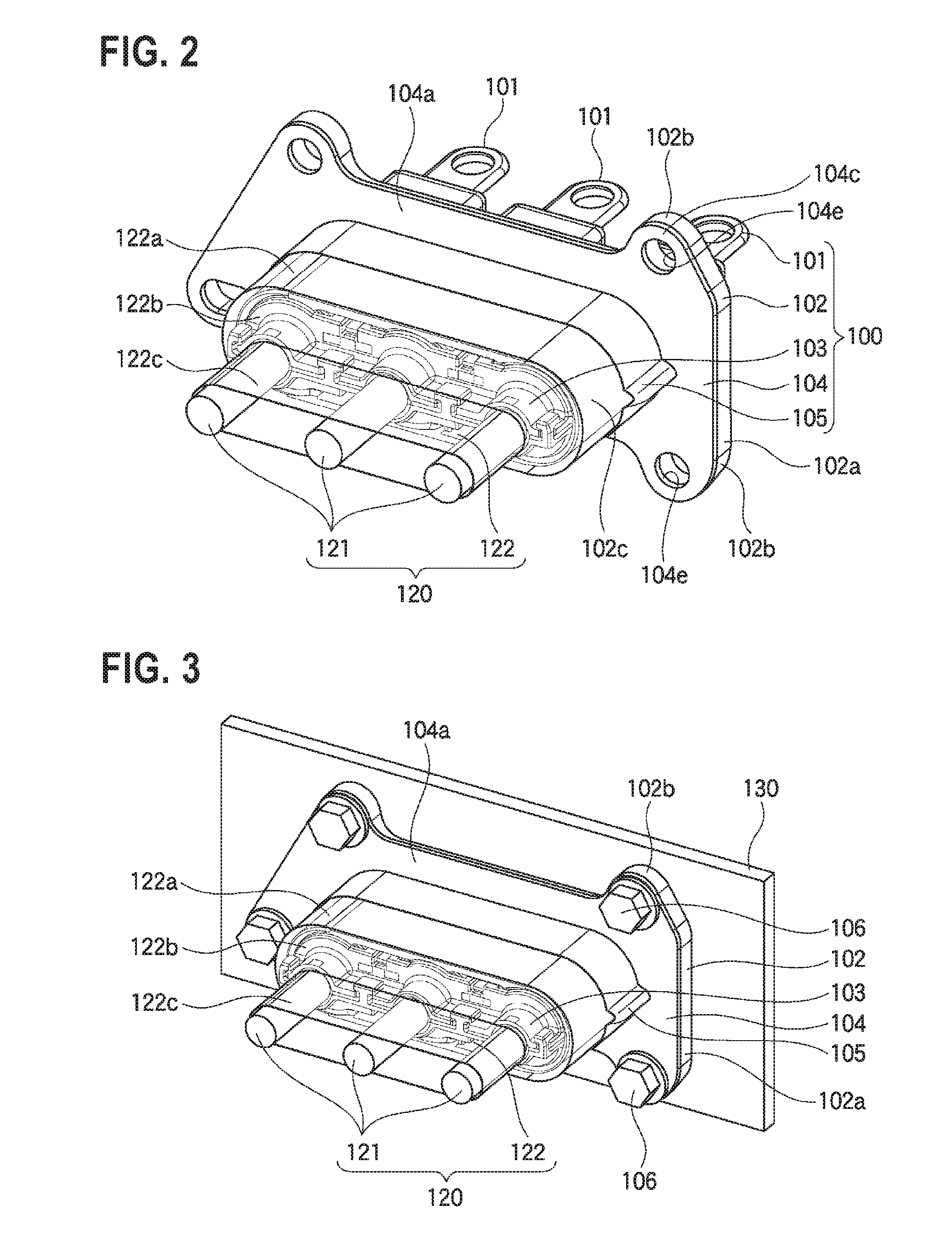
[0053]FIG. 1 is an exploded perspective view of a shield connector with electric wire of the first embodiment of the present invention. FIG. 2 is a perspective view of the shield connector with electric wire of the first embodiment of the present invention. FIG. 3 is a perspective view in which the shield connector with electric wire of the first embodiment of the present invention is attached to a device side case. FIG. 4 is a sectional view in which the shield connector with electric wire of the first embodiment of the present invention is attached to the device side case. FIGS. 5A and 5B are figures to describe a shield shell of the first embodiment of the present invention, in which FIG. 5A is a front view, and FIG. 5B is a perspective view. FIG. 6 is a perspective view which indicates that the shield shell of the first embodiment of the present invention is attached to a housing. FIG. 7 is a perspective view which indicates that a rear holder is attached to the housing of FIG. ...
second embodiment
[0094]The second embodiment of the present invention is different from the first embodiment in the shape of the shield shell. Therefore, in the second embodiment, the shape of the shield shell is described. Members except the shield shell are common to the first embodiment, and their description is omitted. FIG. 9 is a perspective view of the shield shell of the second embodiment of the present invention.
[0095]A shield shell 204 of the second embodiment of the present invention is different from the shield shell 104 of the first embodiment in the shape of bent pieces 204b, as shown in FIG. 9. A shell body 204a, flanges 204c, a through hole 204d and bolt holes 204e are the same as the shell body 104a, the flanges 104c, the through hole 104d and the bolt holes 104e of the shield shell 104 of the first embodiment.
[0096]The bent pieces 204b are plate-like members which are formed by bend-pressing rectangular pieces, which are punch-pressed to extend toward the central side from the inne...
third embodiment
[0102]The third embodiment of the present invention is different from the first embodiment in the shape of the shield shell. Therefore, in the third embodiment, the shape of the shield shell is described. Members except the shield shell are common to the first embodiment, and their description is omitted. FIG. 10 is a perspective view of the shield shell of the third embodiment of the present invention.
[0103]A shield shell 304 of the third embodiment of the present invention is different from the shield shell 104 of the first embodiment in the shape of bent pieces 304b, as shown in FIG. 10. A shell body 304a, flanges 304c, a through hole 304d and bolt holes 304e are the same as the shell body 104a, the flanges 104c, the through hole 104d and the bolt holes 104e of the shield shell 104 of the first embodiment.
[0104]The bent pieces 304b are plate-like members which are formed by bend-pressing rectangular pieces, which are punch-pressed to extend toward the central side from the inner ...
PUM
 Abstract
Description
Claims
Application Information
 - Generate Ideas
- Intellectual Property
- Life Sciences
- Materials
- Tech Scout
- Unparalleled Data Quality
- Higher Quality Content
- 60% Fewer Hallucinations
Browse by: Latest US Patents, China's latest patents, Technical Efficacy Thesaurus, Application Domain, Technology Topic, Popular Technical Reports.
© 2025 PatSnap. All rights reserved.Legal|Privacy policy|Modern Slavery Act Transparency Statement|Sitemap|About US| Contact US: help@patsnap.com