Check patentability & draft patents in minutes with Patsnap Eureka AI!

Analyte sensor

Active Publication Date: 2016-08-25
SENSEONICS INC
View PDF8 Cites 33 Cited by
  • Summary
  • Abstract
  • Description
  • Claims
  • Application Information

AI Technical Summary

Benefits of technology

The patent text describes an input / output circuit that includes a capacitor and a tuning capacitor bank that can adjust the resonant frequency of an LC tank circuit. The circuit also includes an over-temperature protection circuit that can detune the LC tank circuit to reduce power in case of overheating. The technical effect of this invention is to improve the stability and reliability of the input / output circuit, especially in cases where overheating occurs.

Problems solved by technology

However, with no internal power source, the sensor is dormant if the sensor is not located in the proximity of the external device (i.e., if the inductive elements of the sensor and the external device are not coupled within the electrodynamic field generated by the external device).
The sensor would be able to take analyte measurements and convey data to the external device while the patient is wearing the armband, but the sensor would not be able to able to take analyte measurements while the patient was not wearing the armband (e.g., because the human patient is swimming or showering), and the result would be a gap in analyte measurement information.

Method used


Image

  • Analyte sensor
  • Analyte sensor
  • Analyte sensor

Examples


Embodiment Construction

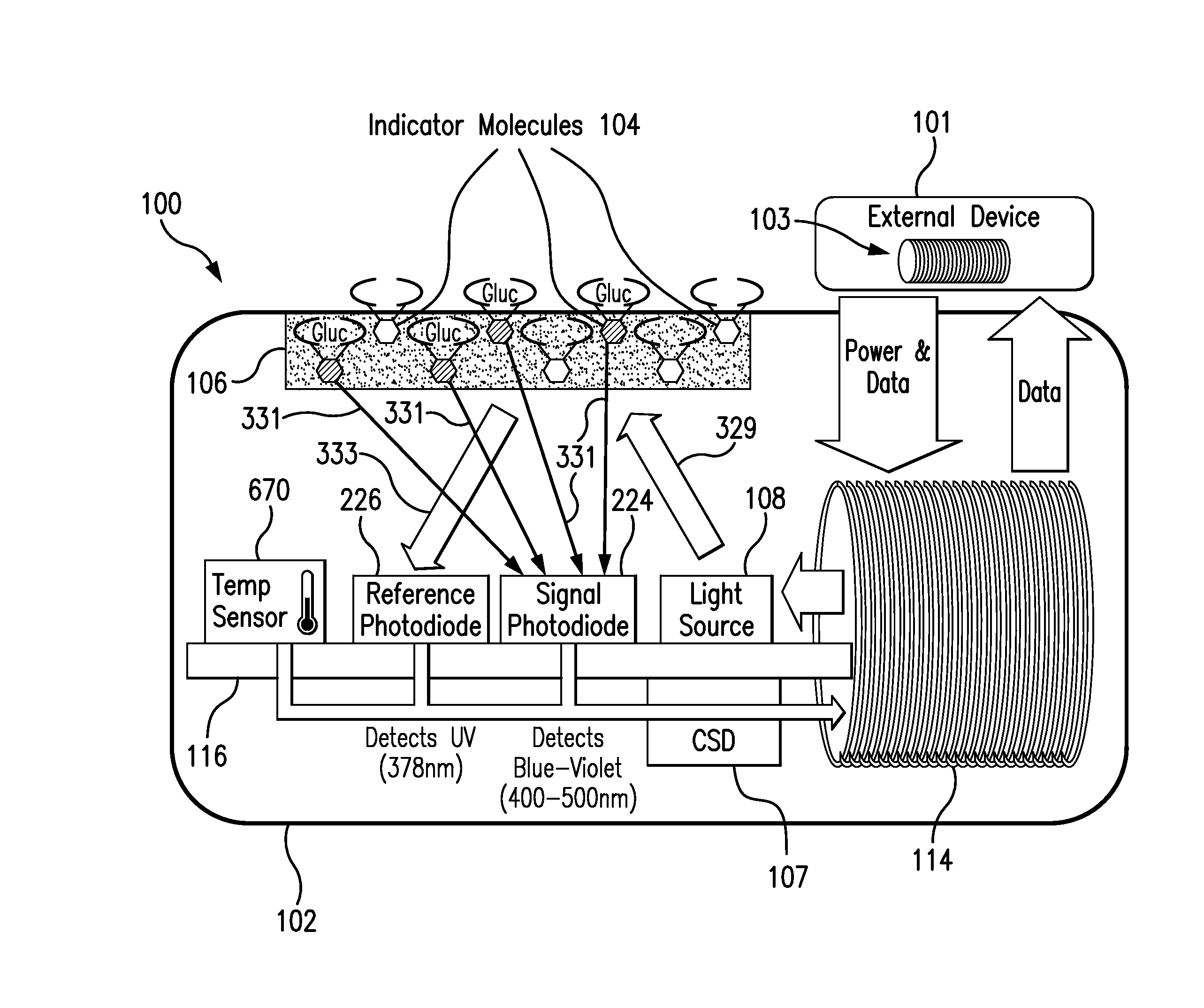
[0031]FIG. 1 is a schematic view of an analyte monitoring system embodying aspects of the present invention. As illustrated in FIG. 1, the system may include an analyte sensor 100 and an external device 101. In some non-limiting embodiments, the sensor 100 may be a fully implantable analyte sensor. The sensor 100 may be implanted in a living animal (e.g., a living human). The sensor 100 may be implanted, for example, in a living animal's arm, wrist, leg, abdomen, peritoneum, intravenously, or other region of the living animal suitable for sensor implantation. For example, in one non-limiting embodiment, the sensor 100 may be implanted beneath the skin (i.e., in the subcutaneous or peritoneal tissues). The sensor 100 may be configured to measure an analyte (e.g., glucose, oxygen, cardiac markers, low-density lipoprotein (LDL), high-density lipoprotein (HDL), or triglycerides) in a medium (e.g., interstitial, intravascular, or intraperitoneal fluids) within the living animal.

[0032]The...


PUM


Abstract

Sensors and methods for measurement of an analyte in a medium within a living animal are described. The sensor may include an inductive element that may receive power from an external device. The sensor may also include a charge storage device (CSD) and a memory. The sensor may perform analyte measurements initiated by the external device using power received from the external device and convey the analyte measurements to the external device using the inductive element. The sensor also may perform autonomous analyte measurements using the on board charge device's power and store the autonomous analyte measurements in the memory. The sensor may convey one or more stored analyte measurements to the external device using the inductive element using power received from the external device. The sensor may include a CSD-powered clock and a CSD-powered measurement scheduler that initiate the autonomous analyte measurements.

Description

BACKGROUND[0001]1. Field of the Invention[0002]The present invention relates to a sensor for obtaining analyte measurements. Specifically, the present invention relates to an implantable sensor and methods of using the same that improve analyte sensor measurement.[0003]2. Discussion of the Background[0004]An implantable sensor that has no charge storage device may rely exclusively on an external device for operational power (e.g., to operate its circuitry for making measurements and conveying the data to the external device). The sensor and the external device may each include an inductive element (e.g., coil). The sensor may receive power from the external device when the external device uses its inductive element to generate an electrodynamic field and the inductive elements of the sensor and external device are magnetically coupled within the electrodynamic field. However, with no internal power source, the sensor is dormant if the sensor is not located in the proximity of the ex...

Claims


Application Information

Patent Timeline
IPC IPC(8): A61B5/145A61B5/00A61B5/1459
CPCA61B5/14532A61B2560/0214A61B5/7225A61B5/1459A61B5/0002A61B5/0075
Inventor DEHENNIS, ANDREWTANKIEWICZ, SZYMONWHITEHURST, TODD
Owner SENSEONICS INC
Features
  • R&D
  • Intellectual Property
  • Life Sciences
  • Materials
  • Tech Scout
  • Unparalleled Data Quality
  • Higher Quality Content
  • 60% Fewer Hallucinations
Learn More