Automated design, simulation, and shape forming process for creating structural elements and designed objects

a technology of structural elements and designed objects, applied in the direction of 3d object support structures, process and machine control, program control, etc., can solve the problems of not allowing for material property design in the z-axis, consuming unnecessary time, materials, and wasting composite parts

Inactive Publication Date: 2016-08-25
FLEMING ROBERT J
View PDF2 Cites 117 Cited by
  • Summary
  • Abstract
  • Description
  • Claims
  • Application Information

AI Technical Summary

Benefits of technology

[0009]FIG. 4 illustrates an example sub-system for implementing resin / fiber control, according to another embodiment.

Problems solved by technology

Composite materials are typically formed into shape via pre-formed molds that are costly and add to the development cycle time.
These steps consume unnecessary time, materials, and waste adding to the cost of composite parts.
This process for generating three-dimensional objects from layered 2C slices is simple and effective but is limited to certain material sets and does not allow for material property design in the z-axis.
It is also difficult to integrate continuous high modulus fibers and high modulus resins into these types of properties.
Another problem with traditional three-dimensional printing processes is that the final properties of the finished part are difficult to predict from the material properties fed into the printer.

Method used


Image

  • Automated design, simulation, and shape forming process for creating structural elements and designed objects
  • Automated design, simulation, and shape forming process for creating structural elements and designed objects
  • Automated design, simulation, and shape forming process for creating structural elements and designed objects

Examples


example

[0075]FIG. 10 illustrates an example of a shaped object produced using a structural element such as described with examples provided herein. In FIG. 10, an object is scanned using a structured sensor scanning device then imported into a software program with algorithms that optimize both the physical properties (e.g. structural and electrical) then optimize the tool path for forming the shaped object. In some embodiments, the sections formed using, for example, a three-dimensional printing tool such as described with an example of FIG. 1, with structural elements include a fiber core or resin exterior which optionally carry conductive traces. With conductive core or traces thereof can be designed into electrical patters which can interconnect or ground electrical components or other elements to form, for example, a printed wiring board.

[0076]The conductive material and the non-conductive material can be deposited using the same robot and head or different head or robot. The conducti...

examples

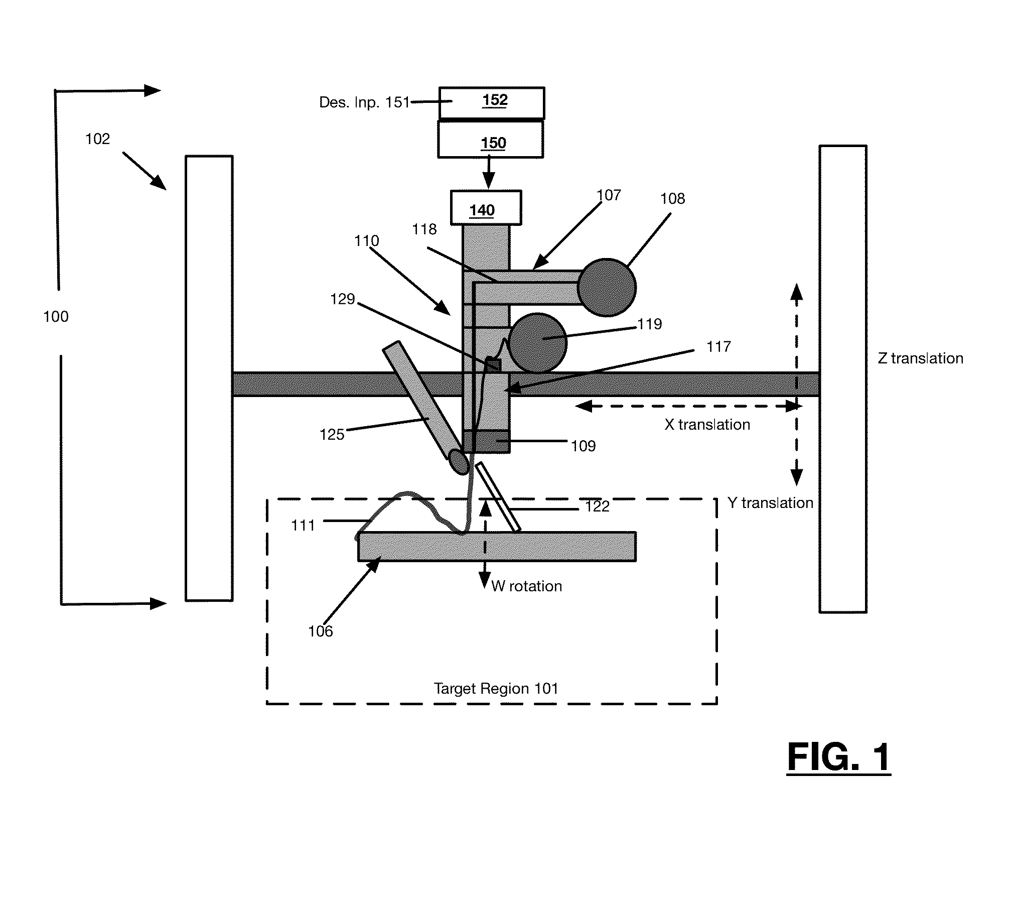
[0077]A 3-axis machine with 3 stepper motors and an Arduino microcontroller was purchased from Inventables.com (Shapeoko 2) the system can move about 6 inches in z-direction, and 18 inches in x and y directions. A small reel of S-glass fiber roving purchased from AGY Inc. Aiken S.C. (ZenTron 758-AB-675) was used as the fiber. The glass roving was pulled from a bobbin and pushed through a tube into a feedblock. The individual fiber was around 10-20 microns in diameter and the roving is around 0.5 mm in diameter The glass roving was pushed in a controlled metering fashion using a stepper motor driven soft wheel and a steel bearing. Simultaneously a UV curable liquid resin was metered into the feedblock using a syringe pump. The feedblock is the manifold where the fiber and liquid resin are intimately mixed before shaping and curing to form a solid shape. The fiber coated with the resin was around 1 mm in diameter when cured. A UV light (Omnicure 2000) was aimed at the exit of the feed...


PUM

PropertyMeasurementUnit
diameteraaaaaaaaaa
diameteraaaaaaaaaa
diameteraaaaaaaaaa

Abstract

A three-dimensional printer, system and method is provided for individually creating three-dimensional structural elements (individually termed fundamental structures) which are sequentially positioned into formation of a shaped object.

Description

RELATED APPLICATIONS[0001]This application claims benefit of priority to U.S. Provisional Patent Application No. 62 / 179,239, filed May 2, 2015. This application is also a continuation-in-part of U.S. patent application Ser. No. 14 / 543,772, filed on Nov. 17, 2014, which claims benefit of priority to U.S. Provisional Patent Application No. 61 / 905,052, filed Nov. 15, 2013. The aforementioned priority applications are hereby incorporated by reference in their respective entireties.TECHNICAL FIELD[0002]Embodiments described herein relate generally to a shape forming process, and more specifically, to a shape forming process, compositions, and applications thereof for creating structural elements and designed objects.BACKGROUND[0003]Composites refer generally to a heterophase material containing a binder and a solid. A growing class of structural composites consist of an organic polymer binder or “resin” and a filament or fiber, typically composed of glass, carbon, or natural fibers such ...

Claims


Application Information

Patent Timeline
Patent Type & Authority Applications(United States)
IPC IPC(8): B29C67/00G05B19/4099G06F17/50
CPCB29C67/0066Y10T428/2933G06F17/50B29C67/0088G05B19/4099B33Y30/00B33Y50/02G05B2219/35134G05B2219/49007B29K2995/0005B29L2031/3425B29K2105/0002B29K2105/122B29C67/0055B29C70/021C08J5/08C08F222/1006H05K1/0284H05K3/0014B33Y10/00B29C67/0085B33Y80/00B29C64/106B29C64/118B29C64/188B29C64/209B29C64/30B29C64/393C03C25/24Y02P90/02G06F30/00
Inventor FLEMING, ROBERT J.VASQUEZ, DANIEL
Owner FLEMING ROBERT J
Why Eureka
Try Eureka