Mobile material elevating system

a technology of material elevating system and mobile material, which is applied in the direction of conveyor parts, supporting frames, transportation and packaging, etc., can solve the problems of significant airborne dust of material, slow pneumatic conveyance, and occupy a lot of space for conveyors, and achieve the effect of quick line up of trailer halves

Inactive Publication Date: 2016-08-25
VITA INT
View PDF6 Cites 18 Cited by
  • Summary
  • Abstract
  • Description
  • Claims
  • Application Information

AI Technical Summary

Benefits of technology

[0008]One variation of the invention described herein is that the truck tractor used to transport the material elevator may be provided with a hydraulic pump system and be connected to the material elevator, negating the need for a motor-driven hydraulic system mounted to the trailer. In this variation, all other facets of the invention remain the same, just the hydraulic source is external rather than on-board.
[0009]In another variation of the invention, the transport trailer is built to be significantly shortened at the operational location by uncoupling that part of the trailer ahead of the forward stabilizers and moving the front, or uncoupled, part of the trailer to a staging area away from where the elevating system is being used. This feature may be desired on operating sites which have a limited amount of area for parking the trailer to which the invention is mounted. In one embodiment, the detaching trailer portion is provided with a lift axle which is normally raised, but which is lowered for the trailer size reduction operation, allowing the truck which delivered the unit to remove that part of the trailer described without having to employ any additional equipment to perform this function. There are various arts that can be used to effect trailer separation, but in one embodiment that is new to the industry, this invention uses a trailer frame-wide pilot pin assembly on one half of the trailer which fits into a guide receptacle on the other half of the trailer, making it possible to quickly line up the trailer halves without exact alignment needed when making the connection. The trailer halves are held together using a hydraulic cylinder-positioned clamp which surrounds the mating flanges of the trailer halves on three sides; additionally, hydraulic cylinder actuated locking lugs hold the last flanged side together.

Problems solved by technology

Downsides to these methods are that conveyors take up a lot of room on a site due to their length and limited incline during operation, whereas pneumatic conveyance is slow and creates significant airborne dust of the material being delivered.
Additionally, pneumatic delivery can degrade the material being delivered by breaking the material as the material impacts itself and / or the structure into which it is being delivered.
The sand is typically pneumatically delivered, but pneumatic delivery releases large quantities of respirable silica dust which, on information and belief, is in the process of being regulated by OSHA to decrease the exposure and subsequent detrimental effects on workers exposed to sand operations at well sites.
As well, when pneumatically delivered, because the silica sand is blown against the interior plates of the sand trailers commonly used in the industry, it is fractured by impact releasing more fines, with fines being less desirable for frac operations.

Method used


Image

  • Mobile material elevating system
  • Mobile material elevating system
  • Mobile material elevating system

Examples


Embodiment Construction

)

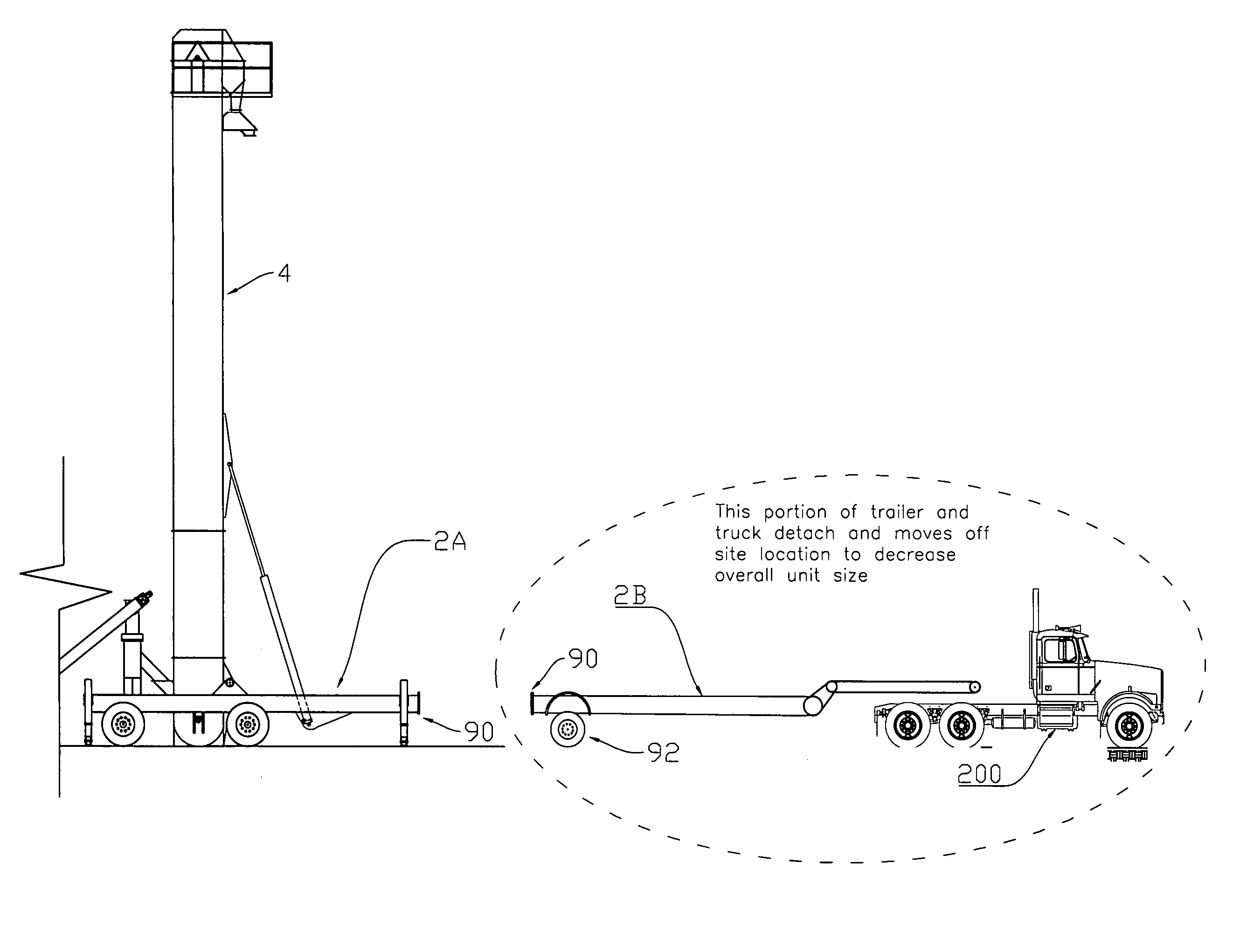
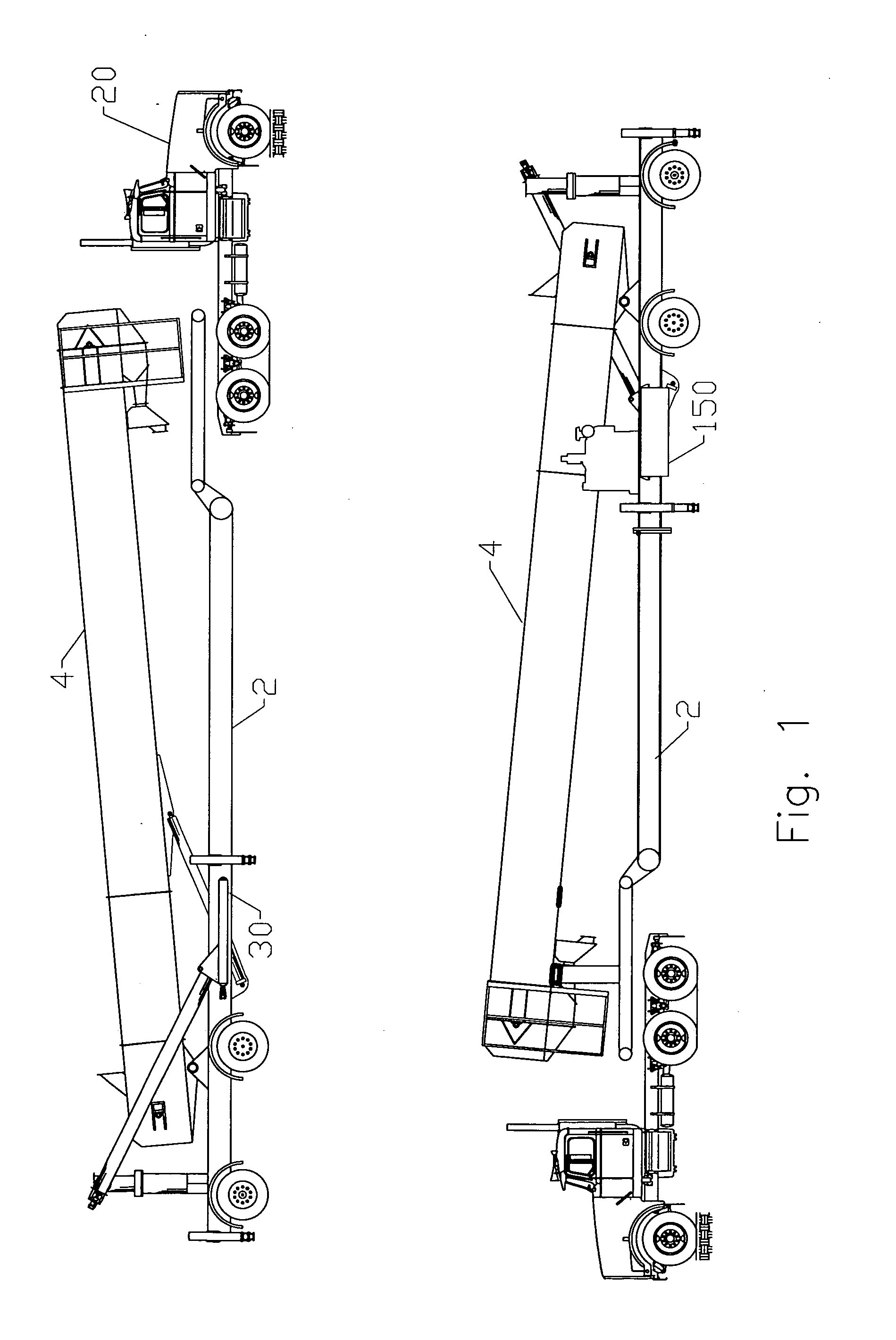
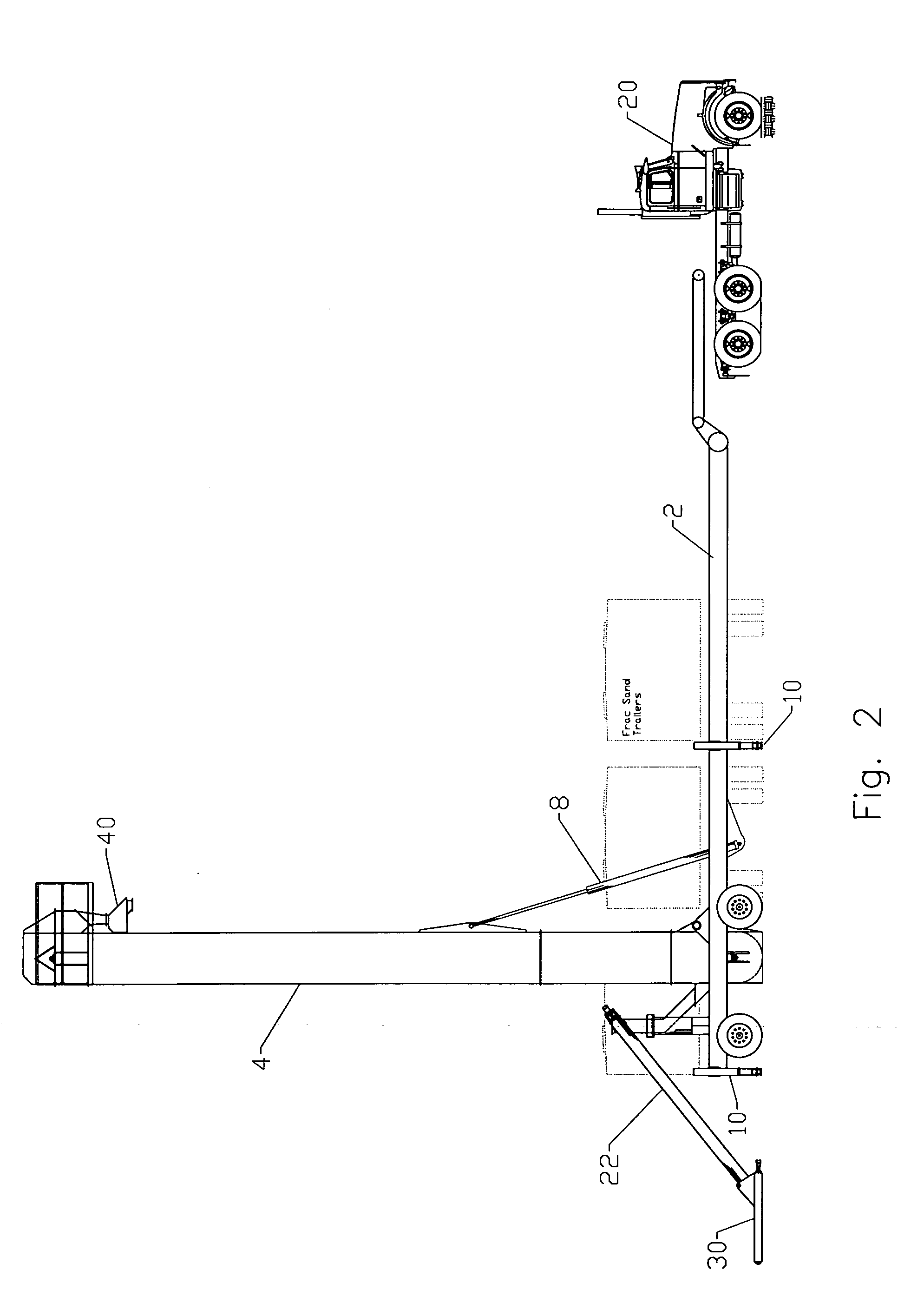
[0030]Embodiments of the invention include a unit-mounted, mobile, self-erecting vertical conveyance (bucket elevator (4) in the embodiment shown, but because other systems such as an auger, chain conveyor, or specialty conveyor belts may be used, bucket elevator (4) is referred to herein as a “vertical conveyance” so as to include those, and other systems known in the art). The bucket elevator (4) of the present invention is an improvement over the prior art in that vertical bucket elevators are typically fixed in nature, mounted on concrete pads, and permanently erected by bolting and guying to adjacent structures or to stabilizing points around the elevator—they are not mobile. In addition, typical elevators are lightweight in their construction, as they are not required to self-erect. The bucket elevator (4) of the present invention embodies a pivot point (6) on the side of the elevator around which it rotates and is held in place, rather than a bolted-down base. The elevator (...


PUM


Abstract

Apparatus for elevating materials that is particularly useful in limited spaces and/or where flexibility in positioning is desirable. Fully self-contained, the apparatus is trailer mounted and provided with a hydraulic system for positioning and powering the individual components as needed to feed material from supply trucks to the apparatus and then to vertically elevate the material for distribution to desired locations as needed for such purposes as, for instance, delivering proppant to site storage for hydraulic fracturing of oil wells. The individual components, including a material-receiving feeder pan, inclined auger, rotatable tower mount, and bucket elevator are preferably trailer-mounted and the bucket elevator is selectively positionable from a first, position for operating and elevating materials to a second position for over-the-road transport.

Description

[0001]This application claims the benefit of U.S. provisional application No. 62 / 118,428, filed Feb. 19, 2015. Application No. 62 / 118,428 is hereby incorporated into this application in its entirety by this specific reference thereto.BACKGROUND OF THE INVENTION[0002]Oftentimes bulk materials delivered to jobsites need to be elevated to allow them to be used, delivered to transport, or stored. At elevation, bulk materials are typically routed to chutes or spouts which guide them to silos or other storage; conveyors, augers, or other means of moving the material; or into trailers, trucks, railcars, or other transport vehicles. As jobsite locations can vary, the means for elevating materials must be mobile and able to be set up as needed. Typical methods for elevating bulk materials via mobile material elevators utilize belt conveyors or pneumatic delivery. Downsides to these methods are that conveyors take up a lot of room on a site due to their length and limited incline during opera...

Claims


Application Information

Patent Timeline
Patent Type & Authority Applications(United States)
IPC IPC(8): B65G41/00B65G43/00B60B35/00B65G47/34B62D33/08B65G17/12B65G47/16
CPCB65G41/002B65G17/126B65G43/00B60B35/00B65G47/34B62D33/08B65G47/16B65G41/00B65G41/008
Inventor RITTER, ALEXANDER F.
Owner VITA INT
Why Eureka
Try Eureka