Compound engine assembly with confined fire zone

Active Publication Date: 2016-08-25
PRATT & WHITNEY CANADA CORP
View PDF6 Cites 23 Cited by
  • Summary
  • Abstract
  • Description
  • Claims
  • Application Information

AI Technical Summary

Problems solved by technology

Compound engine assemblies including a compressor used as a supercharger or turbocharger may define a relatively bulky assembly whic

Method used


Image

  • Compound engine assembly with confined fire zone
  • Compound engine assembly with confined fire zone
  • Compound engine assembly with confined fire zone

Examples


Embodiment Construction

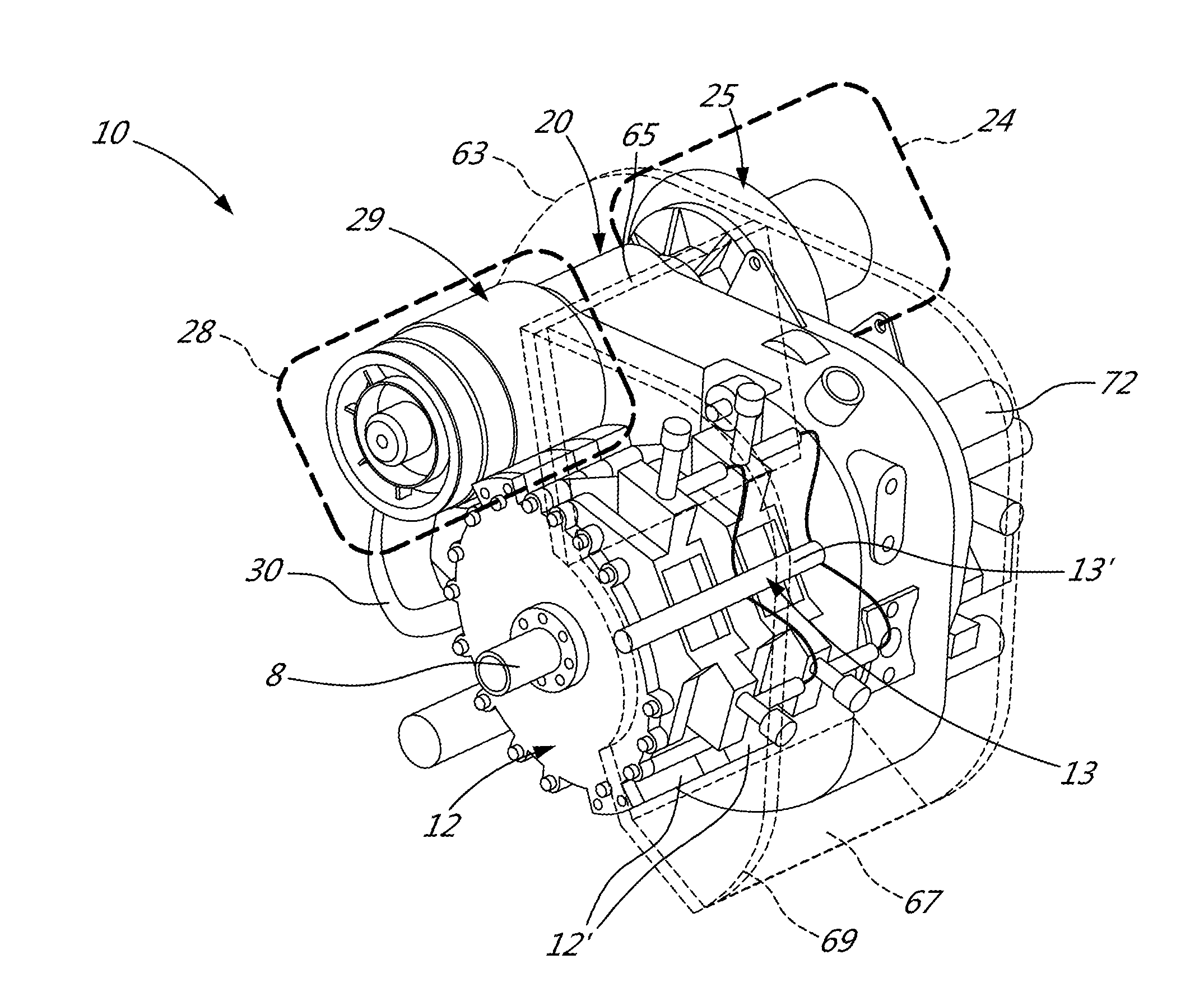
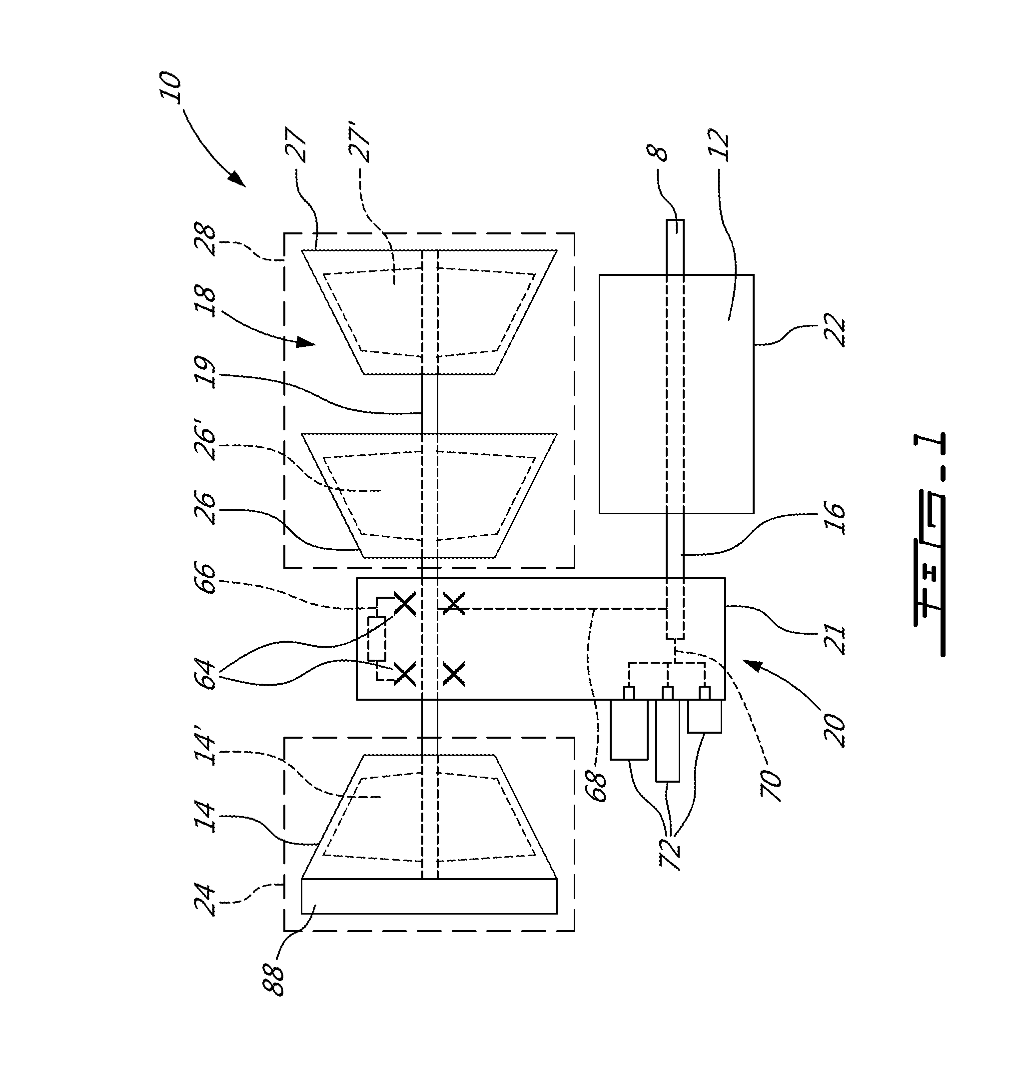
[0020]Referring to FIG. 1, a compound engine assembly 10 is generally shown, including a liquid cooled heavy fueled multi-rotor rotary engine core 12. The engine core 12 has an engine shaft 16 driven by the engine core 12 and driving a rotatable load, which is shown here as a drive shaft 8. The drive shaft 8 may be an integral part of the engine shaft 16, be directly connected thereto, or be connected thereto through a gearbox (not shown). It is understood that the compound engine assembly 10 may alternately be configured to drive any other appropriate type of load, including, but not limited to, one or more generator(s), propeller(s), accessory(ies), rotor mast(s), compressor(s), or any other appropriate type of load or combination thereof.

[0021]The compound engine assembly 10 is configured as a single shaft engine. The term “single shaft” is intended herein to describe a compound engine where all the rotating components (compressor rotor(s), turbine rotor(s), engine shaft, accesso...


PUM

PropertyMeasurementUnit
Pressureaaaaaaaaaa
Volumeaaaaaaaaaa
Ratioaaaaaaaaaa

Abstract

A compound engine assembly with an engine core including at least one internal combustion engine, a turbine section including a turbine shaft in driving engagement with the engine shaft, and a compressor, and a firewall. The compressor is located on one side of the firewall, and the turbine section and the engine core are located on the other side. The assembly may include a gearbox module with the turbine section and the engine core located on a same side of the gearbox module casing and the compressor located on the opposite side of the gearbox module casing, and with the firewall extending from the gearbox module casing. One or more rotatable accessory may be located on a same side of the firewall as the compressor. A method of reducing fire hazard in a compound engine assembly is also discussed.

Description

CROSS-REFERENCE TO RELATED APPLICATIONS[0001]This application claims priority from U.S. provisional application No. 62 / 118,914 filed Feb. 20, 2015, the entire contents of which are incorporated by reference herein.TECHNICAL FIELD[0002]The application relates generally to compound engine assemblies and, more particularly, to supercharged or turbocharged compound engine assemblies used in aircraft.BACKGROUND OF THE ART[0003]Compound engine assemblies including a compressor used as a supercharger or turbocharger may define a relatively bulky assembly which may be difficult to fit into existing aircraft nacelles, thus creating some difficulty in adapting them for aircraft applications.SUMMARY[0004]In one aspect, there is provided a compound engine assembly comprising: an engine core including at least one internal combustion engine in driving engagement with an engine shaft; a gearbox module including a gearbox module casing containing at least one gear train; a turbine section outside ...

Claims


Application Information

Patent Timeline
IPC IPC(8): F02C7/36F02C3/04F23M11/02
CPCF02C3/04F05D2250/312F05D2220/323F05D2300/171B64D27/06F01C1/22F01C11/008F02C6/12F02C7/25F02C7/36B64D2045/009B64D2700/62947F05D2230/51F05D2230/72F05D2260/4031F05D2300/121F23M11/02Y02T10/12
Inventor LAMARRE, SYLVAINJULIEN, ANDREGAUL, MICHAELTHOMASSIN, JEANMEDVEDEV, ILYA B.USIKOV, SERGEYZOLOTOV, ANDREY
Owner PRATT & WHITNEY CANADA CORP
Why Eureka
Try Eureka