
Adjusted navigation

a navigation system and position technology, applied in the field of adjusted navigation, can solve the problems of inability to use this location to correct inertial navigation systems, less accurate, and the position determined by the system tends to increasingly deviate from the real position, and achieves low cost and high overall quality

Inactive Publication Date: 2016-08-25
NEDERLANDSE ORG VOOR TOEGEPAST-NATUURWETENSCHAPPELIJK ONDERZOEK (TNO)
View PDF14 Cites 6 Cited by
  • Summary
  • Abstract
  • Description
  • Claims
  • Application Information

AI Technical Summary

Benefits of technology

The present invention provides a navigation adjustment method and system that can operate independently without requiring a second system to provide a navigation update. The system uses a filter, such as a Kalman filter, to produce accurate navigation state correction values based on sensor measurements. The navigation state estimation unit of a second vehicle can use reference data provided by the navigation system of a first vehicle to significantly improve accuracy. This allows for a high overall quality at relatively low costs, as only the first vehicle needs a high-quality navigation state estimation unit while multiple second vehicles can be used. The method and system can also be used in a set of vehicles where the navigation system of the first vehicle prepares reference data for use by the navigation system of the second vehicles.

Problems solved by technology

As inertial sensors always introduce errors, however small, the position determined by the system tends to increasingly deviate from the real position as time progresses.
This known device has the disadvantage that it is less accurate in situations where the magnetic field is highly uniform.
Further use of this location to correct Inertial navigation systems is therefore not possible.

Method used


Image

  • Adjusted navigation
  • Adjusted navigation
  • Adjusted navigation

Examples


Embodiment Construction

[0048]The present invention is inspired on Ampere's circuital law, which states:

CH·dl=l

in which:

[0049]H is the field strength of the local static magnetic field,

[0050]C is a closed path over which the integration is done,

[0051]dl is a small element of the closed path C,

[0052]I is the net electric DC current flowing through the surface surrounded by the closed path.

[0053]In practical indoor / outdoor situations, usually no DC current flows in the space where navigation takes place. AC currents (power lines) do flow, but these do not pose a problem as their effects in general average out in time and further, power lines usually go in pairs (such that the net AC current is zero). If we apply Ampere's law to closed paths in such a space without net DC currents it then simplifies to:

CH·dl=O

[0054]In U.S. Pat. No. 8,700,326 a method is disclosed how the accelerometer biases of multiple INS (Inertial Navigation System) can be estimated by partial evaluation of the integral in Ampere's law. Th...


PUM


Abstract

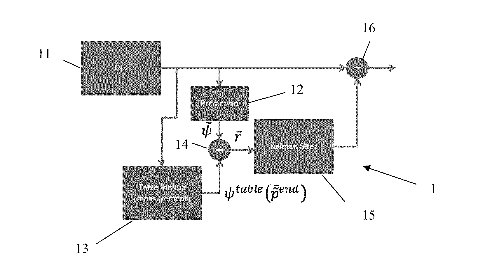
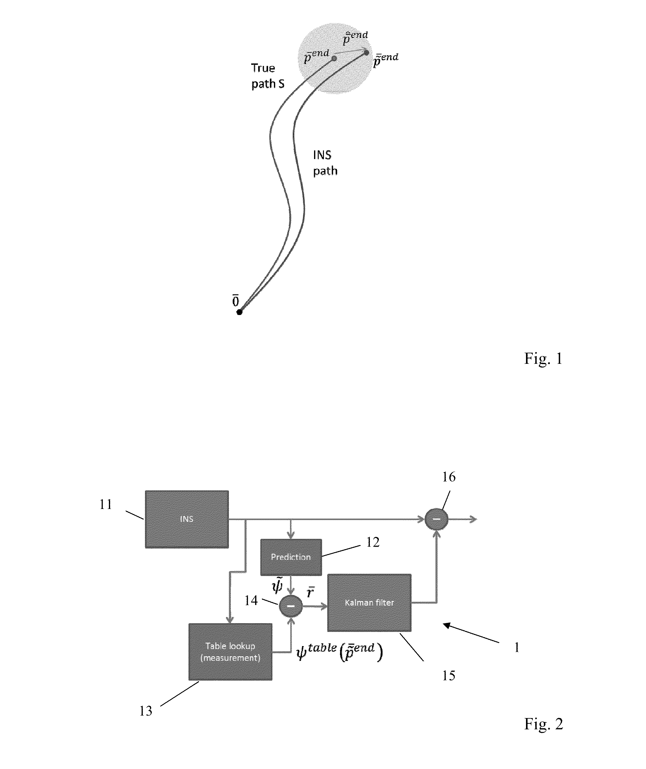
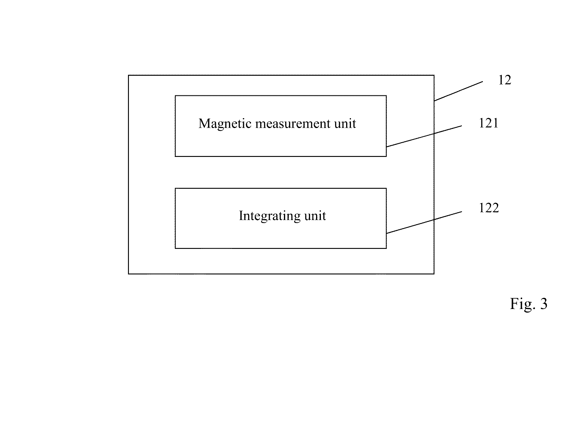
A navigation device (1) comprises:a navigation state estimation unit (11) for repeatedly providing a navigation state estimate comprising at least one of the position, the velocity and the attitude of the device,a prediction unit (12) for providing, using the navigation state estimate, a predicted magnetic property value,a storage unit (13) for retrieving, using the navigation state estimate, a previously stored magnetic property value,a subtraction unit (14) for producing the difference of the predicted magnetic property value and the retrieved magnetic property value,a filter unit (15) for producing, using said difference, a navigation state correction value, anda correction unit (16) for correcting, using said navigation state correction value, a corrected navigation state estimate.The prediction unit (12) comprises:a magnetic measuring unit for repeatedly providing a measured magnetic field strength value, andan integrating unit for integrating the measured magnetic field strength values to produce the magnetic property value corresponding with the navigation state estimate.

Description

BACKGROUND OF THE INVENTION[0001]The present invention relates to adjusted navigation. More in particular, the present invention relates to a method and a device for adjusting the navigation state determined by navigation systems, especially but not exclusively inertial navigation systems. The present invention particularly relates to a method and a device for providing adjusted or corrected navigation states.[0002]Navigation systems are designed to determine their position, and optionally other variables such as velocity, at a certain point in time. Systems such as GPS (Global Positioning System) determine their position with the aid of external references, that is, the locations of satellites. Inertial navigation systems use inertia referenced sensors like accelerometers and gyroscopes, also known as inertial sensors, to determine movements relative to a starting position. The output of an inertial navigation system (such as position, velocity etc.) is determined by numerically in...

Claims


Application Information

Patent Timeline
IPC IPC(8): G01C21/16G01C25/00
CPCG01C21/12G01C25/00G01C21/165G01C21/08G01C21/188G01C21/1654
Inventor RUIZENAAR, MARCEL GREGORIUS ANTHONIUS
Owner NEDERLANDSE ORG VOOR TOEGEPAST-NATUURWETENSCHAPPELIJK ONDERZOEK (TNO)
Learn More