Reception device, reception method, transmission device, and transmission method

a technology of transmission device and reception device, applied in the direction of broadcast information characterisation, distribution switching arrangement, broadcast system characterised by additional data, etc., to achieve the effect of efficiently acquiring components and configuring services

Active Publication Date: 2016-08-25
SATURN LICENSING LLC
View PDF1 Cites 31 Cited by
  • Summary
  • Abstract
  • Description
  • Claims
  • Application Information

AI Technical Summary

Benefits of technology

[0013]According to the first aspect and the second aspect of the present technology, it is possible to acquire components configuring a service efficien...

Problems solved by technology

However, a technique for transmission of components configuring a service (for example, a program) through a ROUTE session is not esta...

Method used


Image

  • Reception device, reception method, transmission device, and transmission method
  • Reception device, reception method, transmission device, and transmission method
  • Reception device, reception method, transmission device, and transmission method

Examples


example 1

(1) Operation Example 1

Basic Broadcasting Service Selection (the Fixed Receiver and Direct Selection)

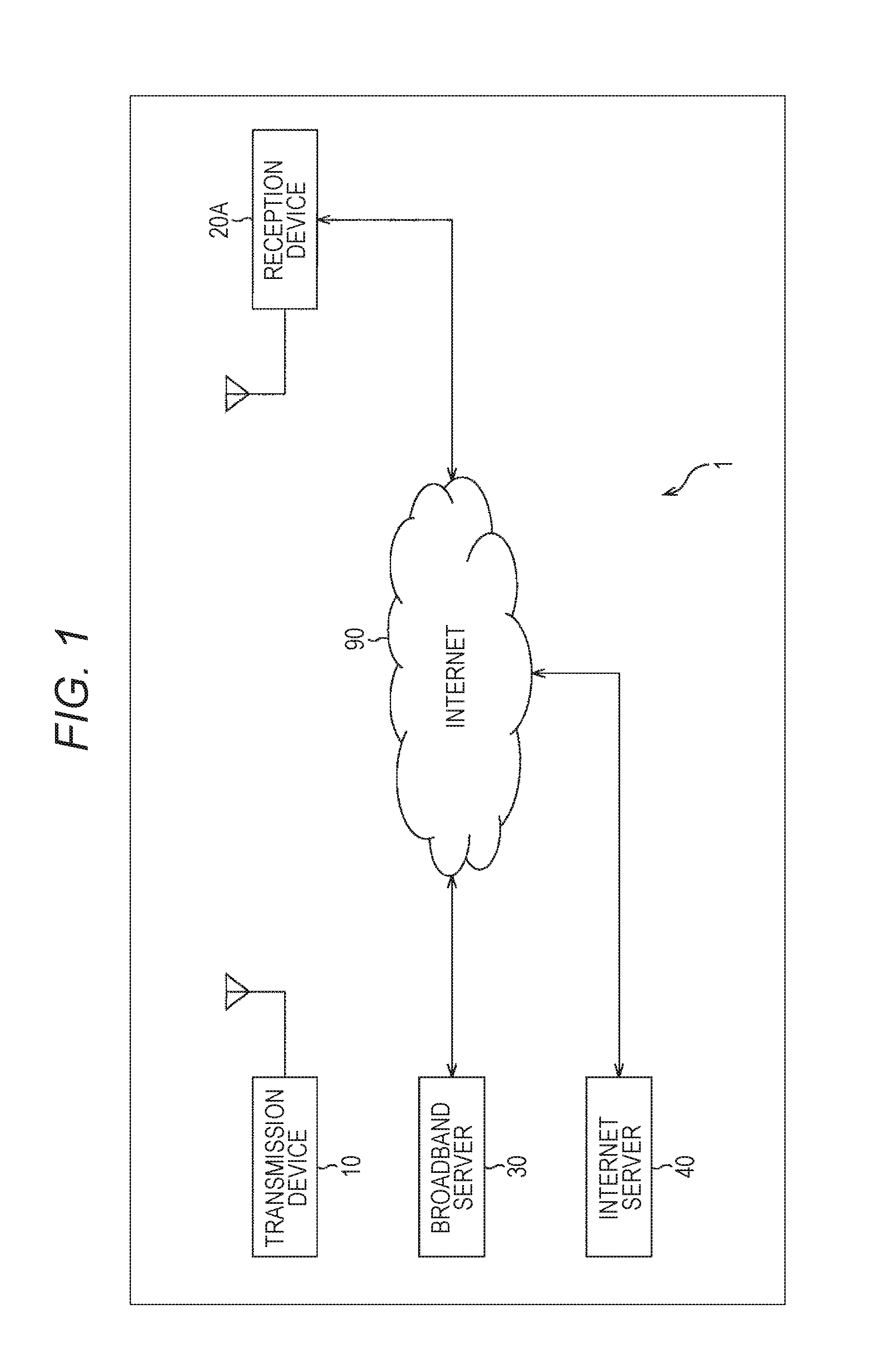
[0125]An operation example 1 is an operation example in which, when components configuring a service are provided only through broadcasting, the service is directly selected in the reception device 20A (FIG. 1) serving as the fixed receiver.

[0126](System Pipe Model)

[0127]FIG. 5 is a diagram illustrating a system pipe model of the operation example 1.

[0128]In FIG. 5, one Base Band Packet (BBP) stream is transmitted through a physical channel (an RF Channel) corresponding to a broadcast wave configured with a predetermined frequency band. In the BBP stream, streams of the LLS, a service channel, an ESG service, and a Network Time Protocol (NTP) are transmitted.

[0129]In the LLS, LLS signaling data of a lower layer that does not depend on a service is transmitted. The LLS signaling data includes, for example, the LLS metadata such as the SCD.

[0130]The service channel (hereinafter, also r...

example 2-1

(2) Operation Example 2-1

Hybrid Service Selection 1 (the Fixed Receiver and Direct Selection)

[0154]An operation example 2-1 is an operation example in which, when the components configuring the service are provided through a hybrid of broadcasting and communication, the service is directly selected in the reception device 20A (FIG. 1) serving as the fixed receiver.

[0155](System Pipe Model)

[0156]FIG. 7 is a diagram illustrating a system pipe model of the operation example 2-1.

[0157]In the operation example 2-1 of FIG. 7, similarly to the operation example 1 of FIG. 5, one BBP stream is transmitted through a physical channel (an RF Channel) corresponding to a broadcast wave configured with a predetermined frequency band. In the BBP stream, streams of the LLS, the service channel (service), the ESG service, and the NTP are transmitted. The service is configured with the SCS signaling data and components of a primary video and a primary audio.

[0158]The broadcast wave having the above co...

example 2-2

(3) Operation Example 2-2

Hybrid Service Selection 2 (the Fixed Receiver and Direct Selection)

[0182]An operation example 2-2 is another operation example in which, when the components configuring the service are provided through a hybrid of broadcasting and communication, the service is directly selected in the reception device 20A (FIG. 1) serving as the fixed receiver.

[0183](System Pipe Model)

[0184]FIG. 9 is a diagram illustrating a system pipe model of the operation example 2-2.

[0185]In the operation example 2-2 of FIG. 9, similarly to the operation example 1 of FIG. 5, one BBP stream is transmitted through a physical channel (an RF Channel) corresponding to a broadcast wave configured with a predetermined frequency band. In the BBP stream, streams of the LLS, the service channel (service), the ESG service, and the NTP are transmitted. The service is configured with the SCS signaling data and the components of the primary video and the primary audio.

[0186]The broadcast wave having...


PUM


Abstract

The present technology relates to a reception device, a reception method, a transmission device, and a transmission method, which are capable of acquiring a component configuring a service efficiently, appropriately, and easily.
A reception device acquires second metadata including first and second flags, the first flag indicating whether or not it is possible to acquire components configuring a service through only first metadata, the second flag indicating whether or not there is a stream of a component transmitted from a server on the Internet by way of communication among the streams of the components configuring the service, the first metadata including information related to a stream of a component transmitted by way of broadcasting through a broadcast wave of digital broadcasting using an Internet Protocol (IP) transmission scheme, acquires the first metadata based on the second metadata, accesses the stream of the component transmitted by way of the broadcasting based on the first metadata, and controls reproduction of the component. The present technology can be applied, for example, to a television receiver.

Description

TECHNICAL FIELD[0001]The present technology relates to a reception device, a reception method, a transmission device, and a transmission method, and more particularly, to a reception device, a reception method, a transmission device, and a transmission method, which are capable of acquiring a component configuring a service efficiently, appropriately, and easily.BACKGROUND ART[0002]In recent years, a digital broadcasting service has started in respective countries (for example, see Patent Document 1). In digital broadcasting standards of respective countries, a Moving Picture Experts Group phase 2-Transport Stream (MPEG2-TS) scheme is employed as a transmission scheme, but in the future, an Internet Protocol (IP) transmission scheme in which an IP packet used in a communication field is used for digital broadcasting is introduced, and a more advanced service is expected to be provided.CITATION LISTPatent Document[0003]Patent Document 1: Japanese Patent Application Laid-Open No. 2008...

Claims


Application Information

Patent Timeline
IPC IPC(8): H04L29/06
CPCH04H60/73H04N21/2381H04N21/438H04L65/608H04L65/1069H04L65/4076H04N21/84H04H20/26H04H20/423H04H20/93H04L65/60H04H2201/40H04L65/611H04L65/65
Inventor KITAHARA, JUNKITAZATO, NAOHISA
Owner SATURN LICENSING LLC
Why Eureka
Try Eureka