
Portable noninvasive inspection device

a non-invasive, portable technology, applied in the field of portable non-invasive inspection devices, can solve the problems of physical and psychological discomfort of the testee, the bulky and inconvenient carrying of the conventional oral cavity inspection process, and the inability to carry around, so as to achieve the effect of easily switching the filter

Active Publication Date: 2016-09-01
NAT CHIAO TUNG UNIV
View PDF4 Cites 5 Cited by
  • Summary
  • Abstract
  • Description
  • Claims
  • Application Information

AI Technical Summary

Benefits of technology

This patent describes a portable noninvasive inspection device that uses a switched filter module and an image sensor to capture different spectral images of an identical target tissue through different filters. The device also has an inner sleeve and an outer sleeve with a light channel between them to offer better imaging quality and a closed surface for the image sensor to avoid abrupt light points. The device is designed with a built-in battery module and wireless transmission module, making it more convenient and mobile for application and operation. The technical effects of this patent are an improved inspection device that can switch filters easily and provide better imaging quality while being portable and wireless.

Problems solved by technology

The conventional oral cavity inspection process is pretty complicated.
Further, as the conventional inspection equipment includes a microscope, it is bulky and inconvenient to carry about.
Besides, the conventional inspection equipment is invasive to oral tissue and likely to cause physical and psychological discomfort to the testee.
Further, the prior-art device cannot store image data but requires the tester to diagnose the target tissue on the spot.
The prior-art device does not allow the tester to change the filter in the observation channel but still requires the tester to diagnose the target tissue on the spot.
In such a scenario, the tester is inconvenient to replace the filter for observing the fluorescent response of the target tissue under a different spectrum of light.

Method used


Image

  • Portable noninvasive inspection device
  • Portable noninvasive inspection device
  • Portable noninvasive inspection device

Examples


Embodiment Construction

[0024]The present invention proposes a portable noninvasive inspection device, which contains a switched filter module and a probe head having an image sensor, wherein a light source is used to illuminate the target tissue and generate an optical inspection signal, and wherein the tester can conveniently select a special filter to filter the optical inspection signal and obtain the filtered image.

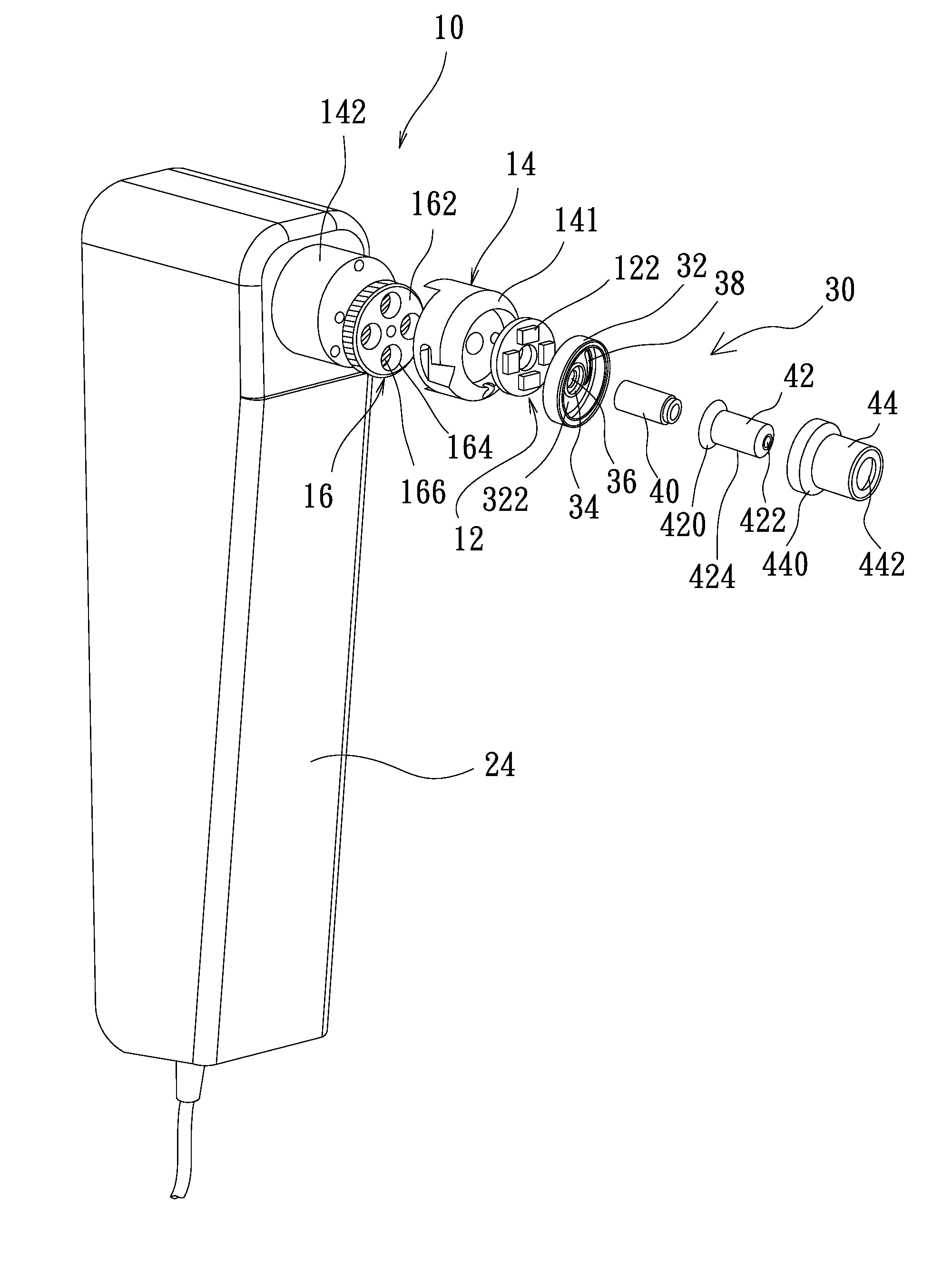
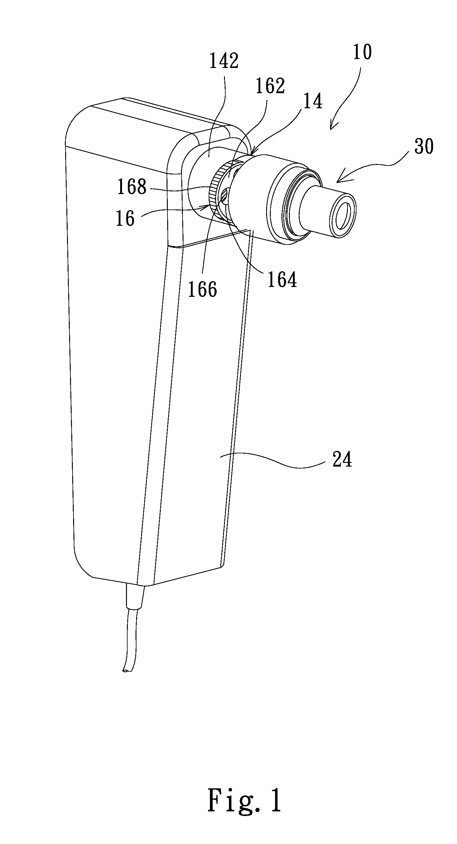
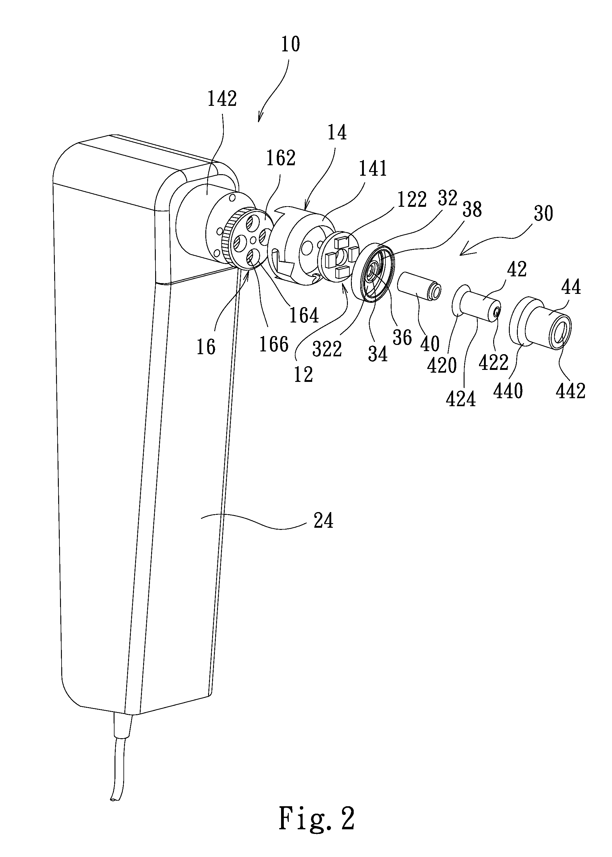
[0025]The present invention proposes a portable noninvasive inspection device 10, which comprises a light source 12, a probe head 14, at least one switched filter module 16 and an image sensor 18. The light source 12 is used to illuminate a target 20 to generate an optical inspection signal. In the embodiment shown in FIGS. 1-3, the light source 12 is arranged at the front end of the probe head 14. The probe head 14 provides the light source 12 with an optical path. The probe head 14 receives the optical inspection signal and transmits the optical inspection signal through the optical path....


PUM


Abstract

The present invention discloses a portable noninvasive inspection device, which comprises a light source illuminates a target to generate an optical inspection signal; a probe head provides an optical path for light source to receive optical inspection signal; a probe tube arranged at a front end of probe head; at least one switched filter module arranged in the optical path, allowing the optical inspection signal to pass there through to generate a corresponding spectral signal; and an image sensor arranged behind the switched filter module, receiving the spectral signal and generating a spectral image. The spectral image can be transmitted to an external device, wherefrom the user can use the spectral image to examine the target in further detail. The present invention features a rotary-type or movable-type switched filter module, which facilitates the user to switch filters easily during optical inspection.

Description

CROSS REFERENCE TO RELATED APPLICATION[0001]This application is a Continuation-in Part of co-pending application Ser. No. 14 / 066,858, filed on Oct. 30, 2013, currently pending, for which priority is claimed under 35 U.S.C. §120 and the entire contents of all of which are hereby incorporated by reference.BACKGROUND OF THE INVENTION[0002]1. Field of the Invention[0003]The present invention relates to a portable noninvasive inspection device, particularly to a portable noninvasive inspection device, which applies to optical inspection, and whose filters can be switched to meet different requirements.[0004]2. Description of the Related Art[0005]With advance of inspection technology, there have been various devices for medical inspection in the market. The physicians can diagnose the patents, referring to the inspection results of the inspection devices. The current inspection technology will be described with the exemplification of oral cavity inspection below.[0006]In the current oral ...

Claims


Application Information

Patent Timeline
Patent Type & Authority Applications(United States)
IPC IPC(8): A61B5/00A61B1/06
CPCA61B5/0071A61B5/0035A61B1/0646A61B1/063A61B2562/12A61B5/0013A61B2560/0425A61B2562/0233A61B2576/00A61B1/0684
Inventor OU-YANG, MANGHUANG, TING-WEIYANG, CHIN-SIANGHSIEH, YAO-FANGLI, SING-TSUNGCHIOU, JIN-CHERNTSAI, MING-HSUIDUANN, JENG-RENLIN, YUNG-JIUNWU, SHUEN-DEYAN, YUNG-JHEHE, ZHENG-LIN
Owner NAT CHIAO TUNG UNIV
Learn More