End cap filtration module, filtration module and filtration system

a technology of filtration module and filtration system, which is applied in membrane technology, ultrafiltration, membranes, etc., can solve the problems of increased friction and higher pressure loss, and achieve the effect of minimizing pressure differences between filtration modules and small footprin

Active Publication Date: 2016-09-01
X FLOW
View PDF1 Cites 1 Cited by
  • Summary
  • Abstract
  • Description
  • Claims
  • Application Information

AI Technical Summary

Benefits of technology

[0013]Hence, an objective of the invention is to provide an end cap which allows a smaller footprint and which minimizes the pressure differences between filtration modules.
[0015]The end cap is configured to transport a main flow from the inlet to the first outlet, wherein a portion of the main flow flows towards an inlet of a filtration module via the second outlet. By providing a flow guide element between the inlet and the first outlet within the chamber at a second outlet side of the chamber to extend a part of the inlet wall to a corresponding part of the first outlet wall it is possible to smoothly guide the main flow from the inlet to the first outlet. As the flow guide element also defines one or more openings, a portion of the main flow is allowed to flow towards the second outlet.
[0016]In absence of the flow guide element, the main flow from the inlet to the first outlet will be distorted by the increase and subsequent decrease of the size of the chamber at the location of the second outlet, which increases friction and causes higher pressure loss. By providing the flow guide element within the chamber at a second outlet side of the chamber, the increase and decrease of the size of the chamber is reduced while still allowing a portion of the main flow to flow towards the second outlet via the one or more openings. Hence, the amount of distortion of the main flow is reduced by using the flow guide element and thus the pressure difference between filtration modules is reduced.
[0017]In an embodiment, the inlet opening and the first outlet opening are similar in shape and / or size. In this way the cross section of the inlet and the cross section of the first outlet are similar which minimizes the distortion and thus the pressure difference between inlet and first outlet. In case the cross section of the inlet and the cross section of the first outlet are substantially equal to each other, the flow guide element preferably has a constant cross section corresponding to a part of the cross section of the inlet and first outlet, so that the main flow is not or minimally disturbed by the flow guide element. In case the cross section of the inlet and the cross section of the first outlet are not equal to each other, the flow guide element preferably gradually changes its cross section from corresponding to a part of the cross section of the inlet at the inlet side of the flow guide element to corresponding to a part of the cross section of the first outlet at the first outlet side of the flow guide element, so that the distortion to the main flow is minimized.
[0019]In an embodiment, the inlet opening and the first outlet opening are aligned with respect to each other. Not only does this minimize the pressure difference caused by the end cap, but it may also provide a smaller footprint compared to an end cap having a non-aligned inlet opening and first outlet opening.
[0023]The outlet channel which extends through the chamber forms a flow resistance negatively influencing the pressure difference between end caps. When the outlet channel is part of or forms an aerodynamically shaped element, the flow from inlet to first outlet is smoothly guided around the outlet channel which reduces the friction and thus the pressure difference between end caps.

Problems solved by technology

In absence of the flow guide element, the main flow from the inlet to the first outlet will be distorted by the increase and subsequent decrease of the size of the chamber at the location of the second outlet, which increases friction and causes higher pressure loss.

Method used


Image

  • End cap filtration module, filtration module and filtration system
  • End cap filtration module, filtration module and filtration system
  • End cap filtration module, filtration module and filtration system

Examples


Embodiment Construction

:

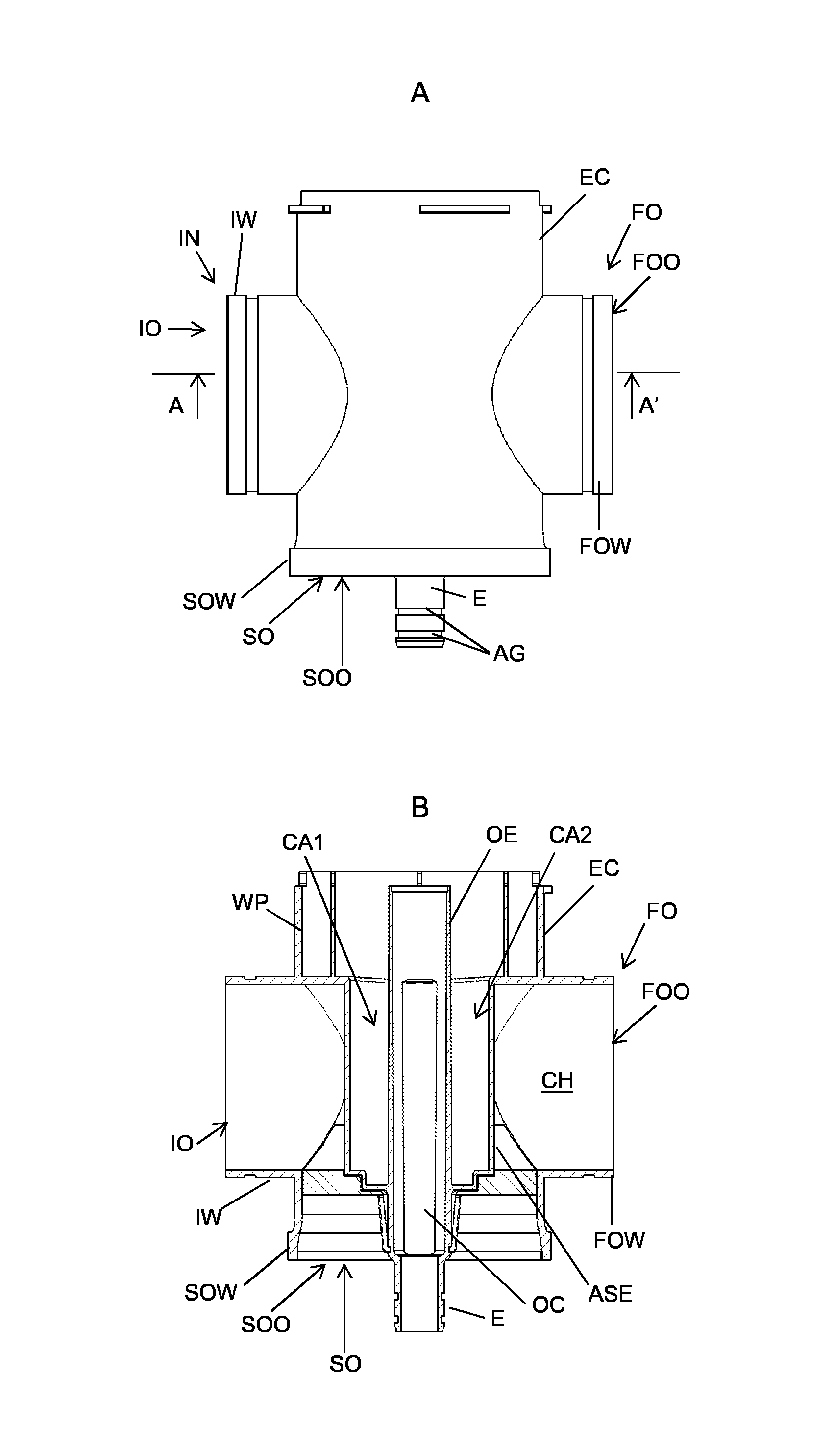
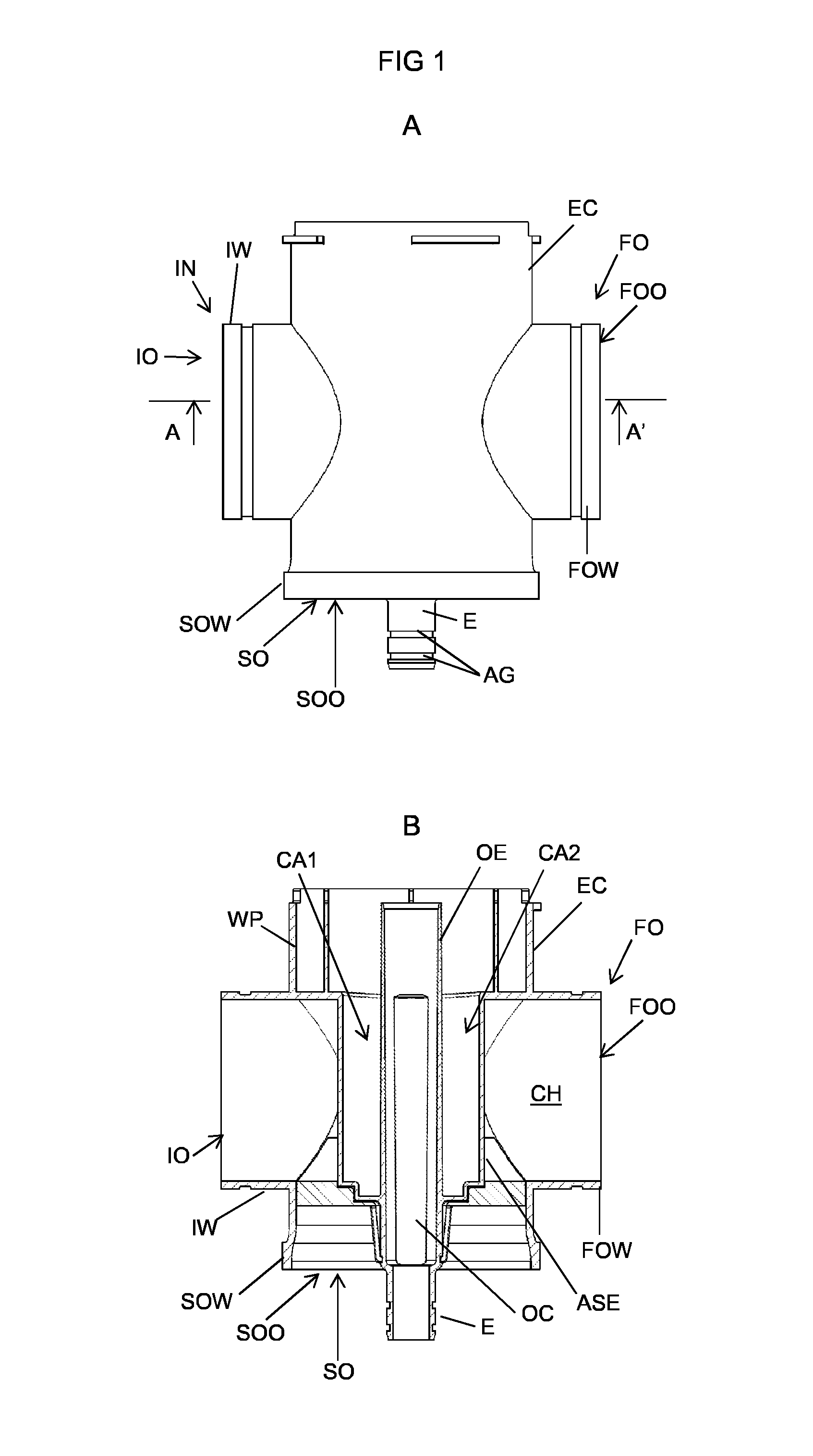
[0049]FIG. 1A, 1B, 2, 3A, 3B, 4, 5A, 5B, 6, 7A and 7B depict an end cap EC according to an embodiment of the invention. FIG. 1A, 1B and 2 are used to highlight the second aspect of the invention. The remaining figures are used to highlight the first aspect of the invention. FIG. 1A, 1B and 2 thus omit the flow guide element characteristic for the first aspect of the invention in order to clearly explain the invention according to the second aspect.

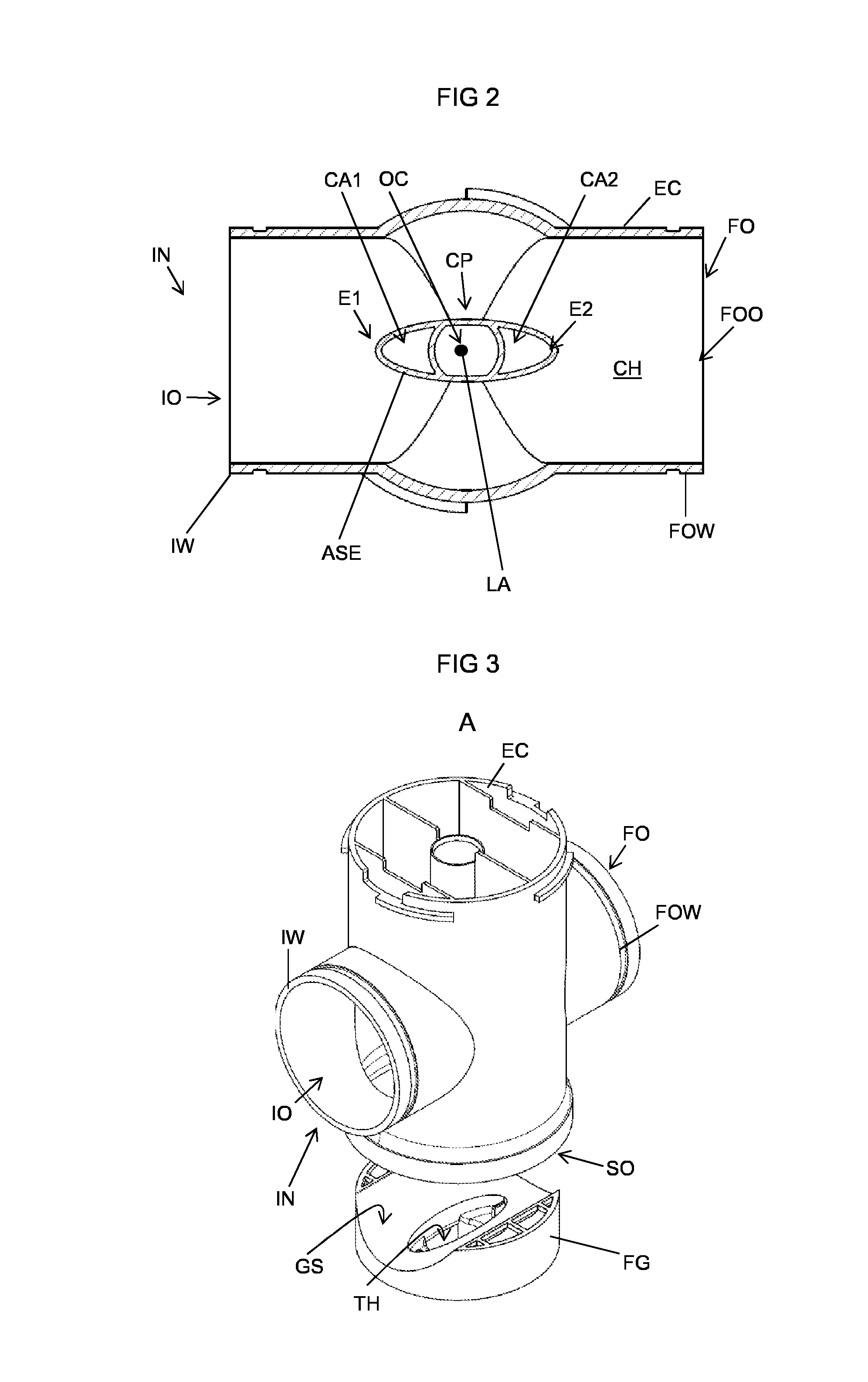
[0050]FIG. 1A depicts a side view of the end cap, FIG. 1B depicts a cross sectional side view of the end cap and FIG. 2 depicts a cross sectional bottom view of the end cap along line A-A′ as shown in FIG. 1A.

[0051]The end cap EC is suitable to be used in combination with a filtration module FM as schematically shown in FIG. 8 which shows a part of a filtration system in cross section to show the interior of the filtration modules and the end caps and allows to explain the flow paths. The end cap EC is also suitable to be used in combinat...


PUM


Abstract

An end cap for a filtration module having a chamber includes an outlet channel extending therethrough which is part of or forms an aerodynamically shaped element having a cross section with an elongated shape mainly directed from the inlet to the first outlet, a width of the elongated shape at both ends thereof being smaller than at a center part of the elongated shape. An end cap may also include an inlet, a first and second outlet, and a flow guide element arranged between the inlet and the first outlet within the chamber at a second outlet side thereof, the flow guide element extending a part of an inlet wall to a corresponding part of a first outlet wall, the flow guide element defining one or more openings allowing a portion of a main flow to flow towards the second outlet.

Description

CROSS-REFERENCE TO RELATED APPLICATIONS:[0001]This application is the National Stage of International Application No. PCT / NL2014 / 050710 filed Oct. 13, 2014, which claims the benefit of Netherlands Application No. NL 2011614, filed Oct. 15, 2013, the contents of which is incorporated by reference herein.FIELD OF THE INVENTION:[0002]The invention relates to an end cap for a filtration module, a filtration module provided with such an end cap, and a filtration system comprising said filtration module with end cap.BACKGROUND OF THE INVENTION:[0003]Filtration modules may be used for the filtration of fluids and are known in a wide variety of variants. A filtration module usually comprises a housing with one or more filter elements, e.g. tubular membranes as shown in U.S. Pat. No. 5,494,577, positioned therein which divide the space inside the housing in a feeding side and permeate side.[0004]One type of filtration module is based upon so-called dead-end filtration in which fluid to be fi...

Claims


Application Information

Patent Timeline
Patent Type & Authority Applications(United States)
IPC IPC(8): B01D63/00B01D63/06
CPCB01D63/00B01D63/06B01D2313/08B01D2313/125B01D2317/04B01D2313/54B01D2313/105B01D2313/21B01D61/08B01D61/18B01D63/02B01D63/10B01D2313/13B01D2313/44
Inventor BLANKERT, BASTIAANBORGERINK, ROB
Owner X FLOW
Why Eureka
Try Eureka