Control using movements

a technology of controlling movement and movement, applied in the field of controlling movement, can solve the problems of high computational processing level, undesirable electrical power, and difficulty in discerning the direction of objects using baseline time-of-flight or array based methods, and achieves the effect of small separation, convenient defining, and convenient determining movemen

Active Publication Date: 2016-09-01
ELLIPTIC LAB
View PDF10 Cites 137 Cited by
  • Summary
  • Abstract
  • Description
  • Claims
  • Application Information

AI Technical Summary

Benefits of technology

[0029]Having the proximity criteria configured such that only gestures close to a screen are detected is beneficial in the context of a computer, particularly a laptop, since false detections from typing on a keyboard can more easily be avoided.
[0148]This arrangement of transducers, which facilitates the defining of a relatively elongate ellipsoidal region and also a relatively spherical region, has been found to give particularly advantageous performance when it is desired to receive approximately linear input movements. The computational requirements to determine the presence of an object inside an ellipse, and to determine radial movement away from or towards an origin, are relatively low compared with three-dimensional tracking requiring the real-time calculation of intersections of multiple quadric surfaces. This provides substantial advantages in terms of reliability and cost of manufacture. As previously mentioned, methods of the invention may also be more robust when complex shapes, such as a human hand, are used as the input object, since they do not need to try to resolve the precise coordinates of a centroid of the object.

Problems solved by technology

Such an approach, however, requires a high level of computational processing in order to track the object.
This need for dedicated processing and electrical power is undesirable; particularly so in the context of resource-constrained mobile devices.
Furthermore, conventional tracking methods may have difficulty in discerning the direction of an object using baseline time-of-flight or array based methods due to the speed at which the object moves, and its continually changing ‘shape’ relative to the transducer setup.
However this is not essential nor indeed typical.
In contrast, single-sensor or few-sensor infrared systems do not have the ability to process echoic profiles, and in detecting a most likely range for an object as it moves along a path, may have large variances in the readouts during the movement.
Due to the fast speed of light, the reflections stemming from those two objects cannot be resolved while keeping a sufficiently wide opening angle, such as is required to capture the movement of a hand.
As a consequence, infrared sensing systems facing this ‘range-smearing’ problem may favour the rigid motion of an object past sensors.
This is in contrast to a light source and sensor (e.g. a camera), which would typically need one or more lenses (e.g. a fish-eye lens) to protrude from the mounting surface in order to obtain a comparably wide field of emission or view; such protrusion can be disadvantageous aesthetically, but also technically due to an increased risk of soiling or damage to the lens or other associated components.
Such operation would be impossible using ordinary infra-red sensors.
However, the centroid of a complex input object such as hand is difficult to identify since, as an object changes its perspective relative to the microphones or speakers of the sensing system, a changing set of surface points are visible to the system.
Hence, any tracking using a non-penetrating system must necessarily lead to a mismatch between the system's understanding of where the centroid or centre position of the input object is, and where the user instinctively understands the object to be.
This is undesirable.
Of course, there may be other boundary conditions and constraints which place additional constraints on the shape of such a detection region in practice, such as the physical location of surfaces of the apparatus.
For example, a person typically finds it difficult to effect a purely linear motion of one hand, as would be required if an input mechanism had several degrees of freedom but a linear input were desired (e.g. moving an on-screen cursor in a straight line when it is capable of being moved in two dimensions).
Slaloming may also occur when using known tracking approaches, based on calculating the intersection of quadric surfaces, if there are even small errors in the time-of-flight estimates.
In practice, such errors are very common, both due to limited bandwidth and to the fact that the object being tracked is never a perfect point reflector.
This would potentially result in the same gesture being used for different functions in different applications, which could be confusing to the user.
Furthermore, a limited set of gestures cannot typically support gestures that are tailored to specific applications.
If a larger, single gesture set were provided, to support a richer range of gestures, it would then suffer increased misclassification rates, because it is harder for the system to distinguish between gestures that would need to be more alike.
It could also lead to user frustration because, for at least some applications, there will be redundant gestures which do not perform any function for that application.

Method used


Image

  • Control using movements
  • Control using movements
  • Control using movements

Examples


Embodiment Construction

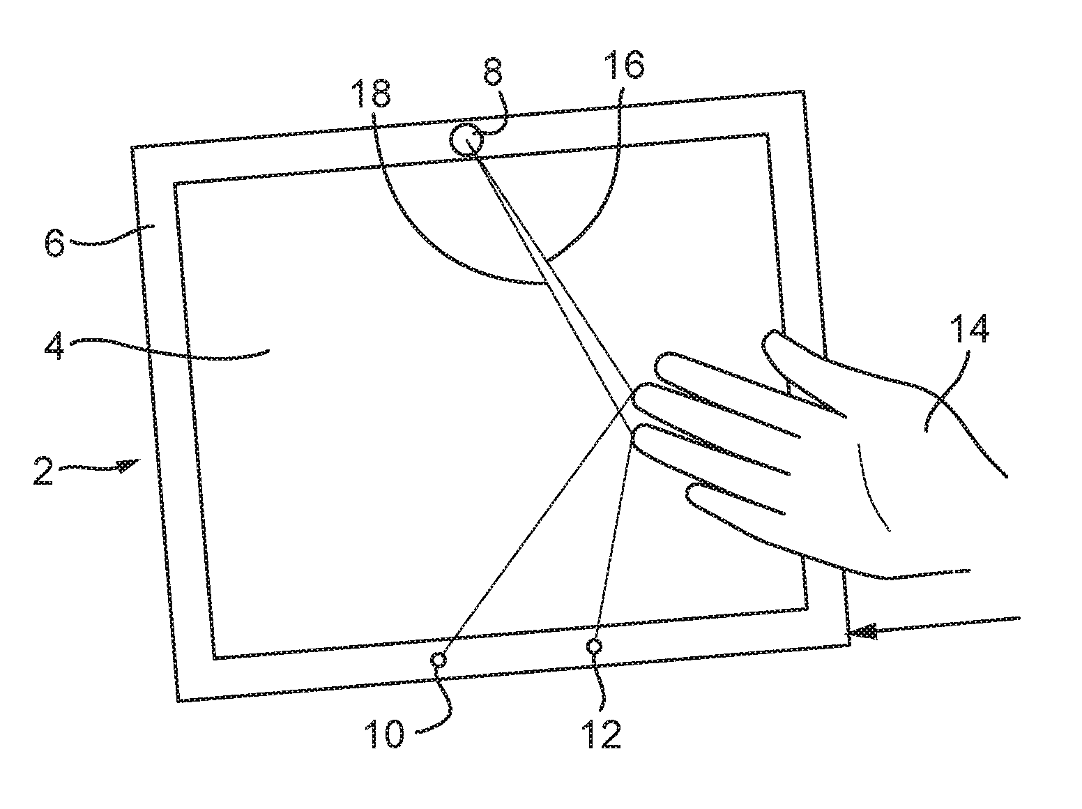
[0166]FIG. 1 shows a gesture-responsive display unit 2 having a stand to the rear (not visible) which keeps it fixed at a slight incline to the vertical. It comprises a flat-panel LCD screen 4, suitable for showing digital photographs, mounted in a frame 6. The top horizontal portion of the frame has, centrally flush-mounted therein, an ultrasound transmitter 8. The bottom horizontal portion of the frame has, flush-mounted therein, a left ultrasound receiver 10 and a right ultrasound receiver 12, located respectively to the left and right of centre.

[0167]In use the transmitter 8 is arranged to transmit ultrasonic pulses at periodic intervals (e.g. every 1 / 100 seconds). The pulses might all be the same, or could, for example, alternate between a higher and a lower frequency. Each pulse lasts for example 10 micro-seconds. The left and right receivers 10, 12 each receive the signals. An inbuilt processor and associated circuitry coordinates the timing of the transmit signals, and also ...


PUM


Abstract

A movement of an object is recognised as a predetermined movement, by transmitting signals between transmitter-receiver pairs, which are reflected from the object. A first event is recorded for one of the transmitter-receiver pairs if a reflected signal meets a predetermined proximity criterion, and a second event is recorded for a second transmitter-receiver pair if, after the first event, a subsequent reflected signal meets a predetermined proximity criterion. The first and second events are used to identify the movement.

Description

CROSS REFERENCE TO RELATED APPLICATIONS[0001]This application is a continuation of U.S. application Ser. No. 14 / 569,300, filed Dec. 12, 2014, which in turn is a continuation of U.S. application Ser. No. 13 / 382,898, filed on Apr. 24, 2012. U.S. application Ser. No. 13 / 382,898 is the National Stage of International Application No. PCT / GB2010 / 001215, filed on Jun. 21, 2010. All of these applications are hereby incorporated by reference in their entirety.BACKGROUND OF THE INVENTION[0002]This invention relates to methods and apparatus for identifying a predetermined movement of an object; in particular, in some embodiments, for identifying a gesture by a human hand for the purposes of providing a gesture-based user interface to an electronic device.[0003]It is known to track the movement of an object, such as a user's finger or hand, by transmitting a succession of signals (e.g. ultrasound pulses) from one or more transmitters, receiving reflected signals at one or more receivers, and tr...

Claims


Application Information

Patent Timeline
Patent Type & Authority Applications(United States)
IPC IPC(8): G06F3/01G06F3/043G06F3/0484G06F3/0488
CPCG06F3/017G06F2203/04108G06F3/043G06F3/0484G06F3/04883G06F2203/04101H04N21/422H04N21/44218H04N21/42204H04N21/42206H04N21/42221G06F3/0325
Inventor DAHL, TOBIAS
Owner ELLIPTIC LAB
Why Eureka
Try Eureka