Sintered powder metal part having radially-extending spaced openings and method of making thereof

a technology of radially extending spaced openings and metal parts, which is applied in the direction of mechanically actuated clutches, gearing details, mechanical apparatus, etc., can solve the problems of time-consuming and high cost of (1) drilling or piercing the hub to form lubrication holes, and (2) machining a tubular lubrication reservoir to achieve the effect of reducing the number of machining

Inactive Publication Date: 2016-09-08
SKN SINTER METALS LLC (US)
View PDF5 Cites 1 Cited by
  • Summary
  • Abstract
  • Description
  • Claims
  • Application Information

AI Technical Summary

Benefits of technology

[0005]An improved way of forming radial through holes and lubricant reservoirs is disclosed herein using powder metallurgy and only minimal machining. In short, the powder metal is compacted into a form having a toothed profile in which at least some or all of the tooth roots are particularly deep on one face of the hub. On the other face of the hub, one or more grooves are machined that intersect at least some of these tooth roots. At these points of intersection, the tooth roots and the groove or grooves from a plurality of radially-extending spaced openings that can be used to permit transport of lubricant from one side of the hub to the other. Moreover, the groove or grooves can serve as a lubricant reservoir, meaning that a greater area of the hub does not need to be removed to provide a reservoir.

Problems solved by technology

However, this process of (1) drilling or piercing the hub to form lubrication holes followed by (2) machining a tubular lubrication reservoir can be both expensive and time-consuming.

Method used


Image

  • Sintered powder metal part having radially-extending spaced openings and method of making thereof
  • Sintered powder metal part having radially-extending spaced openings and method of making thereof
  • Sintered powder metal part having radially-extending spaced openings and method of making thereof

Examples


second embodiment

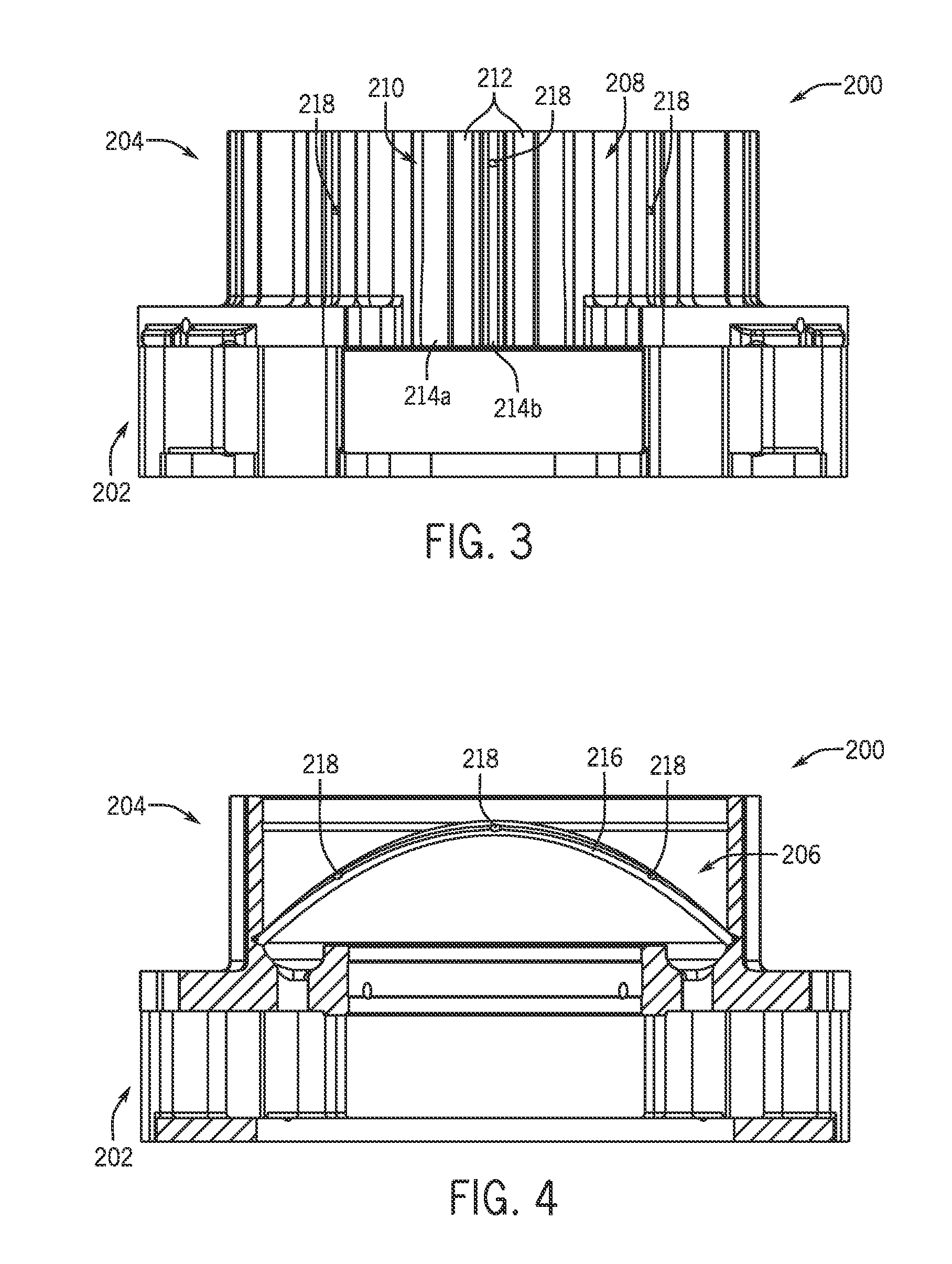
[0036]Referring now to FIGS. 3 and 4, a sintered powder metal part 200 is illustrated in which the geometry of the toothed profile 210 has been modified to alter the number and shape of radially-extending openings 218. In this embodiment, only some of the tooth roots 214b in the toothed profile 210 on the radially-outward facing surface 208 of the hub 204 are deep enough to intersect with the groove 216 on the radially-inward facing surface 206 of the hub 204. As shown in the half of the part 200 illustrated in FIGS. 3 and 4, only three radially-extending openings 218 are formed through the side wall of the hub 204.

[0037]With additional reference to FIGS. 5 and 6, the variance in the depth of the tooth roots 214a and 214b in the second illustrated embodiment from FIGS. 3 and 4 can be seen in greater detail. As can be seen in FIGS. 5 and 6, some of the tooth roots 214a are shallow, whereas others of the tooth roots 214b are comparably deeper. FIGS. 5 and 6 include a cross section tak...

third embodiment

[0039]Turning now to FIGS. 7 and 8, a third embodiment is illustrated. In this sintered powder metal part 300, the toothed profile 310 on the radially-outwardly facing surface 308 of the hub 304 is regular, having teeth 312 and tooth roots 314 that occur in a regular pattern. Accordingly, when a groove 316 is formed or machined into the radially-inward facing surface 306, the circumferential spacing of the radially-extending openings 318 is more regular and only oscillates in the axial direction (as the groove 316 is made to oscillate axially as it circumferentially extends along around the hub 304).

[0040]Yet another variation on the sintered powder metal part is illustrated in FIG. 9. In this sintered powder metal part 400, the groove 416 is formed as a simple annular ring in the radially-inward facing surface 406 of the hub 404 and has a circumference in a plane perpendicular to the central axis of the hub 404. Because the toothed profile 410 is regular, the intersection of the gr...


PUM

PropertyMeasurementUnit
angleaaaaaaaaaa
circumferenceaaaaaaaaaa
depthaaaaaaaaaa

Abstract

A sintered powder metal part and a related method of making the part are disclosed. The sintered powder metal part, which is formed from a compacted and sintered powder metal, includes a hub having a radially-outwardly facing surface and a radially-inward facing surface. A toothed profile is formed in one of the radially-outwardly and radially-inward facing surfaces of the hub. One or more grooves are machined into the other of the surfaces of the hub such that the toothed profile and the one or more grooves are on oppositely-facing radial sides of the hub. The groove or grooves intersect with at least some of the tooth roots of the toothed profile to form a plurality of radially-extending spaced openings through the hub.

Description

CROSS-REFERENCE TO RELATED APPLICATION[0001]This application claims the benefit of the filing date of U.S. Provisional Patent Application No. 61 / 891,998 filed Oct. 17, 2013, which is hereby incorporated by reference for all purposes.BACKGROUND[0002]This disclosure relates to sintered powder metal parts and methods of making such parts. More specifically, this disclosure relates to ways of forming radially-extending spaced openings through a hub of a powder metal part so as to, for example, accommodate transport of oil or other lubricant from one radial side of the hub to the other.[0003]In certain components, it is necessary to have oil or lubrication holes through the component to permit the flow of oil or lubricant from one place in the assembly to another place in the assembly. For example, in a clutch hub, oil is to be supplied from one side of the clutch hub to a clutch pack. In order to do this, a hub of the clutch hubs is conventionally drilled or pierced to produce a pathway...

Claims


Application Information

Patent Timeline
Patent Type & Authority Applications(United States)
IPC IPC(8): F16H57/04B22F3/24B22F5/08B22F3/16
CPCF16H57/0427B22F3/16B22F3/24B22F5/08F16D13/644B22F2003/245B22F2998/10F16D13/74F16H57/043B22F5/10B22F3/02B22F3/10
Inventor TAYLOR, ALAN C.LEMKE, JEFFREY W.
Owner SKN SINTER METALS LLC (US)
Why Eureka
Try Eureka