Asymmetrical impulse drive

a technology of impulse drive and asymmetrical force, which is applied in the direction of instruments, machines/engines, cosmonautic vehicles, etc., can solve the problems of inability to exert substantial and significant linear force to be useful as a drive apparatus, complicated art devices, and further reduce their efficiency, so as to achieve the effect of reducing maintenance costs, reducing maintenance costs, and reducing machining costs

Inactive Publication Date: 2021-04-22
HAMPTON STEVEN MICHAEL
View PDF0 Cites 1 Cited by
  • Summary
  • Abstract
  • Description
  • Claims
  • Application Information

AI Technical Summary

Benefits of technology

[0019]Another object of the present invention is to provide an apparatus for converting rotary motion into linear motion in a self-contained unit capable of propelling an attached vehicle in a desired straight-line direction which can be varied from time to time as desired.
[0020]A further object of the present invention is to provide an apparatus of the character described which is open, compact and sturdy with a minimum of moving parts subject to friction and wear thus requiring a minimum of maintenance and ease of maintenance and assembly.
[0021]A still further object of the present invention is to provide an apparatus of the character described which is relatively inexpensive and requires a minimum of machining.
[0022]Other objects and features of advantage will become apparent as the specification progresses, and from the claims.

Problems solved by technology

Numerous attempts have been made to propel a drive apparatus and attached vehicle along a linear path with the apparatus using unbalanced centrifugal forces generated by gyratory action within the apparatus.
However, the known devices are incapable of exerting a substantial and significant linear force to be useful as a drive apparatus.
Also, the prior art devices often are complicated and have excessive internal friction which further reduces their efficiency.
The prior art also does not have a substantial axial displacement which is tantamount to producing thrust in rotary to linear systems, nor have a means for negating back forces.

Method used


Image

  • Asymmetrical impulse drive
  • Asymmetrical impulse drive
  • Asymmetrical impulse drive

Examples


Embodiment Construction

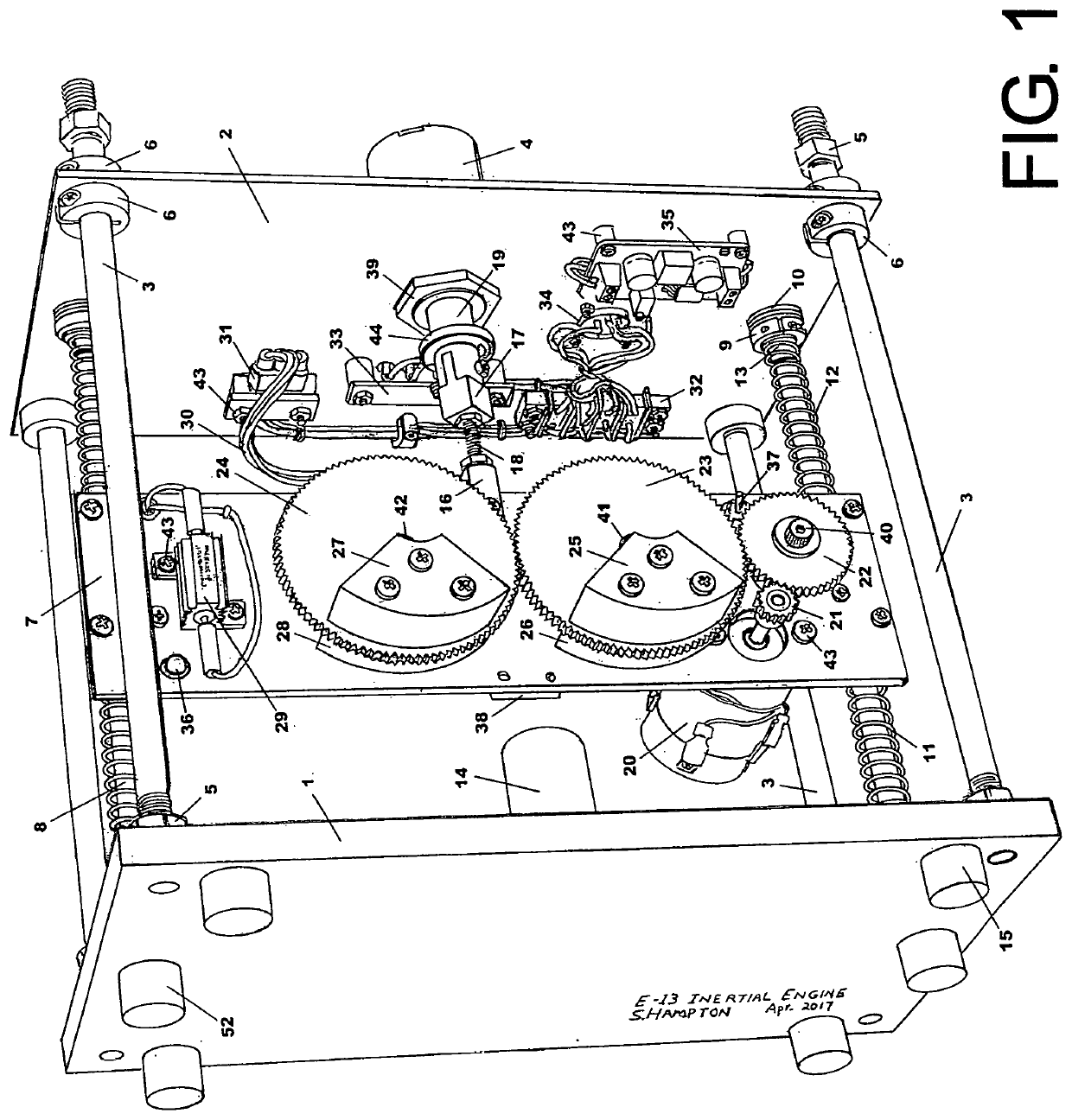
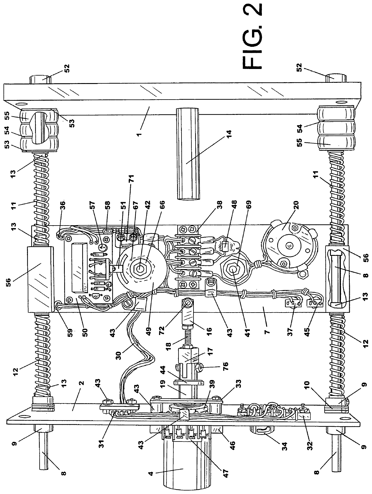
[0034]In FIG. 1, the mainframe assembly comprises of a base plate 1 at left joined to a thrust plate 2 far right by a plurality of mainframe support stanchion rods, straps, angled rails, or plates 3. The mainframe stanchions 3 may also hold an additional cover plate above the thrust plate 2 to offer protection to the solenoid 4 coil and its housing. Solenoid 4 may also be heat-sinked to the thrust plate with heat sink compound or radial heat sink fins. In the illustrated example, the mainframe stanchions 3 that join base plate 1 and the thrust plate 2 may employ fastening devices such as threaded nuts 5, rod clamps 6 or other means to secure the assembly. The use of stanchions 3 give the apparatus strength, durability and allows for easy stroke distance adjustments and disassembly for maintenance or repair.

[0035]The carriage 7 (at center) is suspended by a plurality of glide rods 8 that are secured to the thrust plate 2 by means of rod clamps 9 (far lower right) or other such fasten...


PUM


Abstract

Electric In-Space propulsion uses no fuel. Thrust is generated as impulses where in space, momentum is additive. Rotary motion is converted into bi-linear oscillation of a carriage then its momentum rectified: The carriage is shifted forward during low inertia, so momentum used to oscillate the carriage forward is conserved to be used later in the cycle. Reverse carriage oscillations are deflected. This creates only a pulsed demand on the electric power supply—thus too fulfilling the law of Conservation of Energy: Newton's third law of motion is upheld because action and reaction are not simultaneous events, so in this engine, the inertial delay occurs at post carriage shift during part of the rotors' orbit—when centrifugal force emerges: The centripetal force of the rotors are cyclically nullified by the shift resulting in surges of centrifugal force.

Description

BACKGROUND OF THE INVENTION1. Field of the Invention[0001]This invention relates to self-contained apparatus for converting rotary motion into linear motion, and more particularly to devices utilizing unbalanced centrifugal forces in such a manner to result in moving the device along a linear path.2. Description of the Prior Art[0002]Numerous attempts have been made to propel a drive apparatus and attached vehicle along a linear path with the apparatus using unbalanced centrifugal forces generated by gyratory action within the apparatus. However, the known devices are incapable of exerting a substantial and significant linear force to be useful as a drive apparatus. The interrelationship of their component parts produces forces which tend to cancel out each other with little or no resultant linear force being exerted. Also, the prior art devices often are complicated and have excessive internal friction which further reduces their efficiency. The prior art also does not have a subst...

Claims


Application Information

Patent Timeline
Patent Type & Authority Applications(United States)
IPC IPC(8): F03G3/00
CPCF03G3/00B64G1/409B64G1/285G01G3/00G01G21/00H02G11/003
Inventor HAMPTON, STEVEN MICHAEL
Owner HAMPTON STEVEN MICHAEL
Why Eureka
Try Eureka