Manufacturing Method Of Vacuum Nozzle

A manufacturing method and technology for vacuum suction nozzles, which are applied in the field of vacuum suction nozzle manufacturing, can solve problems such as drill bit wear, poor hole shape, and rising manufacturing costs, and achieve the effects of eliminating processing costs, reducing defects, and solving static electricity phenomena.

Inactive Publication Date: 2017-04-12
PECOTEK
View PDF8 Cites 2 Cited by
  • Summary
  • Abstract
  • Description
  • Claims
  • Application Information

AI Technical Summary

Problems solved by technology

[0004] In order to process ultra-fine micro-holes of 70 μm in polyimide semiconductor vacuum nozzles, it is necessary to perform drilling with a high-speed spindle. However, there are limitations to forming micro-holes by drilling, and such as Figure 7 As shown, during processing, poor hole shape and size are frequently generated due to heat, thereby increasing the manufacturing defective rate
[0005] In addition, if Figure 8 As shown, when processing ultra-fine micro-holes on polyimide vacuum nozzles, the drill bit will be frequently worn, and the drill bit needs to be replaced after 30 to 40 times of drilling
In particular, depending on the characteristics of the drilling process, there is a large cutting resistance in the initial stage, and at this time, micro drills with small outer diameters often break
like Figure 9 As shown, such wear and tear can lead to expensive replacement of micro-drills, resulting in increased manufacturing costs
[0006] In addition, in the soldering process of miniaturized semiconductor chips, due to the disadvantage of static electricity in plastic materials, it is not easy to release the semiconductor chip after it is adsorbed, and it cannot be soldered to an accurate position. High heat will reduce the wear resistance of the tip end of the nozzle, causing many manufacturing defects in the production of semiconductor chips
[0007] Korean Laid-Open Patent No. 2012-0028635 discloses a technology of using polyimide powder instead of polyimide general-purpose material and filling the polyimide powder into a mold for high-temperature treatment. However, this technology is difficult to apply to the requirements The problem of the vacuum nozzle of the present invention with precise dimensional control, for which there is a high demand for technical improvement

Method used


Image

  • Manufacturing Method Of Vacuum Nozzle
  • Manufacturing Method Of Vacuum Nozzle
  • Manufacturing Method Of Vacuum Nozzle

Examples


Embodiment 1

[0100] Polyimide powder (Evonik, Austria) with an average particle size of 150 μm was subjected to uniaxial compression at a pressure of 290 MPa for 10 seconds using a compression molding machine (Core-hole Co., Korea) equipped with a core for vent tube formation forming. The thus molded mixture was heated up to 380° C. at a rate of 2.1° C. / minute, maintained for 30 minutes, and then furnace-cooled. The cooled molded product was dipped in a molten mixture of tin and aluminum in a weight ratio of 14:86, and then taken out. Put it into a high-temperature isostatic pressing machine (AIP, the United States), raise the temperature to 300°C at a heating rate of 1.25°C / min, and raise the pressure to 120MPa at a raising rate of 0.4MPa / min with argon gas for 4 hours high temperature isostatic pressing. Next, the molding was mounted on a horizontal lathe and the tin-aluminum coating on the surface was removed by chipping away with a superhard tool, and a tapered tip was formed at one ...

Embodiment 2

[0102] Dry ball milling was performed after adding 1 g of alumina (Sumitmo, Japan) to 100 g of polyimide (Evonik, Austria). The average particle diameter of the polyimide was 150 μm, and the average particle diameter of the added alumina was 0.4 μm. Alumina balls were used for the dry ball milling, and ball milling was performed at 90 to 100 rpm for 24 hours to manufacture a polyimide mixture. Next, the mixture was subjected to uniaxial compression molding at a pressure of 290 MPa for 10 seconds using a pressure molding machine (Core-hole Co., Korea) equipped with a vent tube forming core. The thus molded mixture was heated up to 380° C. at a rate of 2.1° C. / minute, maintained for 30 minutes, and then furnace-cooled. The cooled molded product was dipped in a molten mixture of tin and aluminum in a weight ratio of 14:86, and then taken out. Put it into a high-temperature isostatic pressing machine (AIP, the United States), raise the temperature to 300°C at a heating rate of 1...

Embodiment 3

[0104] It manufactured by the same method as Example 2 except having added 1 g of zirconium dioxide (TOSOH, Japan). The average particle diameter of the zirconium dioxide added was 0.3 μm.


PUM

PropertyMeasurementUnit
particle sizeaaaaaaaaaa

Abstract

The present invention relates to a manufacturing method of a vacuum nozzle and the vacuum nozzle manufactured by the method, in particular to the manufacturing method of the vacuum nozzle characterized by being manufactured by the compression molding of the polyimide powder and the high temperature isostatic pressing, instead of being manufactured by the cutting processing of the polyimide blocks, thereby improving the yield and reducing the reject ratio.

Description

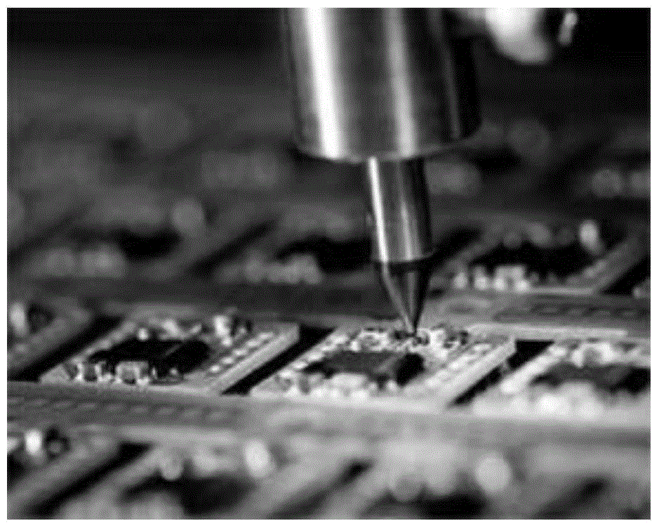
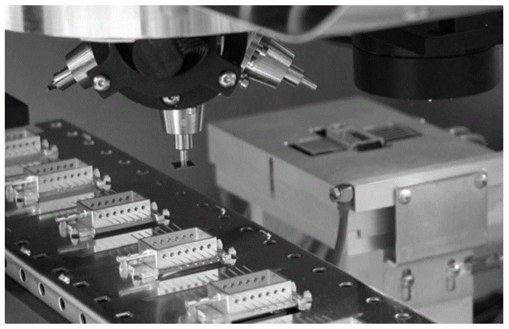
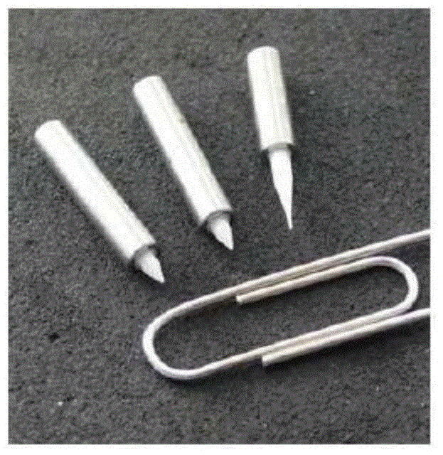
technical field [0001] The present invention relates to a method of manufacturing a vacuum nozzle and a vacuum nozzle manufactured by the method, in particular to a method of manufacturing a vacuum nozzle which is not carried out by cutting a polyimide block Manufacturing, but by compression molding of polyimide powder and high-temperature isostatic pressing to increase yield and reduce defective rate. Background technique [0002] Such as figure 1 with figure 2 As shown, as a material of a vacuum nozzle for mounting a semiconductor chip to a package, metal, ceramics, or engineering plastics are used. However, if image 3 The metal and ceramic vacuum nozzles shown above will cause damage such as dents to semiconductor chips due to their high hardness, and will also cause cracks in chips whose thickness has become thinner due to semiconductor integration. To prevent these phenomena, such as Figure 4 As shown, a buffer mechanism is inserted for manufacturing, but this s...

Claims


Application Information

Patent Timeline
Patent Type & Authority Applications(China)
IPC IPC(8): B29C43/00
CPCB29C43/003B29C43/006B29C2043/5808
Inventor 李香伊金学范姜成旴黃盛昱
Owner PECOTEK
Why Eureka
Try Eureka