Method of providing a flanged connection

a technology of flanged connection and flange, which is applied in the direction of flanged joints, fastening means, couplings, etc., can solve the problems of affecting the quality of flanged connection, so as to achieve the effect of flexibleness

Inactive Publication Date: 2007-12-13
PARKER HANNIFLIN
View PDF4 Cites 0 Cited by
  • Summary
  • Abstract
  • Description
  • Claims
  • Application Information

AI Technical Summary

Benefits of technology

[0015] A flange of any one of a variety of sizes may ...

Problems solved by technology

This considerably increases costs, for both acquisition and maintenance of the plurality of tooling sets required.
However, machining to produce the undercut requires machi...

Method used


Image

  • Method of providing a flanged connection
  • Method of providing a flanged connection
  • Method of providing a flanged connection

Examples


Embodiment Construction

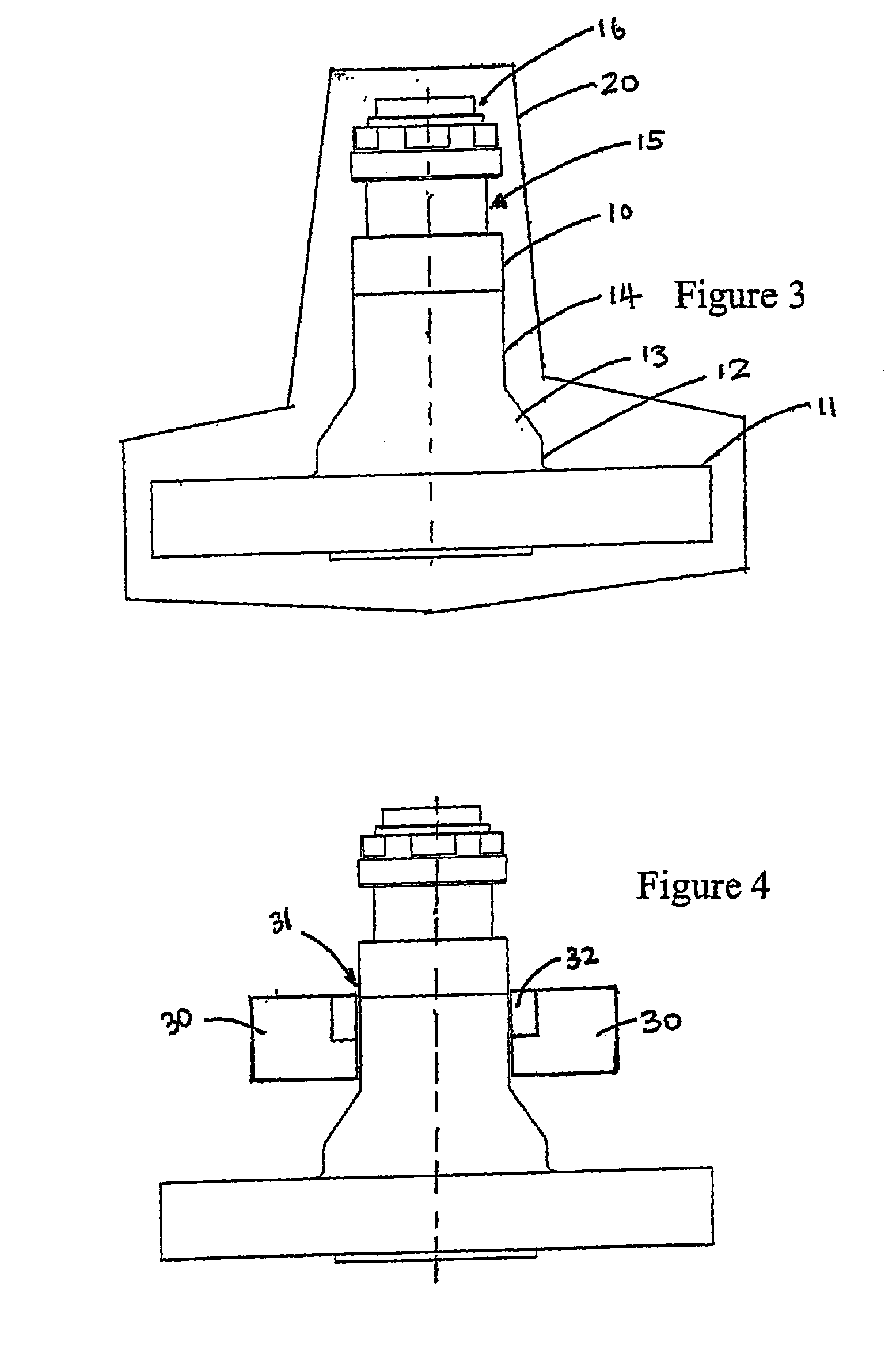
[0029]FIG. 3 is a cross-sectional view of a shaft 10 with an integral flange 11. The line 20 shown around the shaft 10 and integral flange 11 shows the shape that is typically achieved by lower cost open die forging of this component. As can be seen, only minimal machining is required to achieve the final shape. The shaft 10 of this example is connected to integral flange 11 by a base portion 12. A frusto-conical portion 13 interconnects the base portion 12 to a main portion 14 of the shaft. The main portion 14 of this example has an annular groove 15 to accommodate split rings for securing a flange with an aperture (to be described later). It should be noted that the groove and / or split ring do not have to have a square / rectangular section nor does it need to be a pair of split rings or even necessarily a complete ring, it could be just half a ring for example. Above the main portion 14 is an optional arrangement 16 to mate with another component to be joined to the complete double...


PUM


Abstract

A method of providing a flanged component and a flanged component constructed by such method. The method includes providing a shaft, providing a flange with an aperture, passing the aperture of the flange over the shaft and securing the flange to the shaft. The flange may be provided at one end portion of the shaft and a connector may be provided at the other end portion of the shaft to connect the flanged component to another component. The connector may be, for example, an integral flange, a further flange with an aperture or a threaded end portion of the shaft.

Description

CROSS REFERENCE TO RELATED APPLICATIONS [0001] This application is continuation of co-pending International Application No. PCT / GB06 / 000310 filed Jan. 27, 2006, which application designated the United States, and which application claims priority to Great Britain Patent Application No. 0502164.7, filed Feb. 2, 2005, the disclosure of each of which applications is incorporated herein by reference.BACKGROUND OF THE INVENTION [0002] The present invention relates to the provision of a flanged component. The flanged component may have a flange, as shown at 1 and 2, provided on each axial side of an undercut, 3, to provide a twin flanged component as shown in the cross sectional view of FIG. 1. [0003] The flanges and undercut generally, but not exclusively, have a circular cross-section. At least one of the flanges is provided with holes therethrough as shown by the broken lines such as referenced at 4 in FIG. 1. The holes are generally provided around the circular periphery of the flange...

Claims


Application Information

Patent Timeline
IPC IPC(8): B23P11/00F16B21/00F16D1/06F16L23/028
CPCF16B21/00Y10T29/49947F16L23/0286F16D1/06
Inventor DAVIS, MATHEW
Owner PARKER HANNIFLIN
Why Eureka
Try Eureka