Receiver and Collapsible Buttstock for a Firearm

Active Publication Date: 2016-09-08
HUANG GEORGE +1
16 Cites 21 Cited by

AI-Extracted Technical Summary

Problems solved by technology

However, the typical buttstock can be relatively heavy and cumbersome.
The known locking mechanisms used to lock the buttstock in a desired position along the buffer tube are awkward and difficult to operate.
Thus, users are not able to separate components of the firearm, in a typica...

Method used

[0107]In certain exemplary, nonlimiting embodiments, as illustrated in FIG. 19, the extension rod/rail apertures 118 may be at least partially internally lined with a bushing or liner element 125, comprising a plastic, self-lubricating plastic, or other material to reduce friction between the interior walls of the extension rod/rail apertures 118 and the exterior surface of the extension rods/rails 170.
[0120]By utilizing rod dimples/detents 177 and a rod channel 175, the strength and integrity of the extension rods/rails 170 is maintained and the problems introduced by cut notches in existing collapsible stocks is circumvented. Because the majority of the strength of a rod is in the outer perimeter, by utilizing circular dimples/detents that are cut or pressed into the rod, the rod is more structurally sound than a rod having a large, flat cut across the rod.
[0123]By utilizing one or more latch elements 140, a smooth, ball bearing-type action is provided to the lock mechanism. This system provides reduced contact surface friction and smoother and easier manipulation of the components, particularly when compared to a square/rectangular notch.
[0147]When a user desires to extend the buttstock assembly, the user merely urges the latch 130 upward, along the longitudinal axis ALL, to the disengaged or unlocked position. Because of the convenient position of the engagement portion 132 of the latch 130, intentional manipulation of the latch 130 can be accomplished easily, with the user's finger, thumb, or another surface.
[0157]In this manner, the extension rods/rails 170 are aligned along either side of the bore axis of the receiver, causing the majority of...

Benefits of technology

[0034]The presently disclosed invention separately provides a receiver and collapsible buttstock that provides increased strength and rigidity when compared to known retrofit collapsible stock de...

Abstract

A receiver having an integral stock connector component that extends along the receiver; two extension rod/rail apertures formed through the integral stock connector component, wherein each extension rod/rail aperture is formed so as to slidably receive an extension rod/rail extending from a buttstock, such that each extension rod/rail is slidably movable within one of the extension rod/rail apertures; wherein each extension rod/rail comprises a rod channel and two or more rod dimples/detents formed along the rod channel; and a latch that is movable between an engaged position and a disengaged position, wherein when the latch is in the engaged position, a protrusion portion urges latch elements into the rod/rail apertures a distance that seats the latch elements into the rod dimples/detents, and wherein when the latch is in the disengaged position, the protrusion portion allows the latch elements to retract from the rod dimples/detents and into the rod channels.

Application Domain

Breech mechanismsButts

Technology Topic

CHEEK DIMPLESEngineering +1

Image

  • Receiver and Collapsible Buttstock for a Firearm
  • Receiver and Collapsible Buttstock for a Firearm
  • Receiver and Collapsible Buttstock for a Firearm

Examples

  • Experimental program(1)

Example

[0096]For simplicity and clarification, the design factors and operating principles of the receiver and collapsible buttstock according to this invention are explained with reference to various exemplary embodiments of a receiver and collapsible buttstock according to this invention. The basic explanation of the design factors and operating principles of the receiver and collapsible buttstock is applicable for the understanding, design, and operation of the receiver and collapsible buttstock of this invention. It should be appreciated that the receiver and collapsible buttstock can be adapted to many applications where a receiver and collapsible buttstock or strap can be used.
[0097]As used herein, the word “may” is meant to convey a permissive sense (i.e., meaning “having the potential to”), rather than a mandatory sense (i.e., meaning “must”). Unless stated otherwise, terms such as “first” and “second” are used to arbitrarily distinguish between the elements such terms describe. Thus, these terms are not necessarily intended to indicate temporal or other prioritization of such elements.
[0098]The term “coupled”, as used herein, is defined as connected, although not necessarily directly, and not necessarily mechanically. The terms “a” and “an” are defined as one or more unless stated otherwise.
[0099]Throughout this application, the terms “comprise” (and any form of comprise, such as “comprises” and “comprising”), “have” (and any form of have, such as “has” and “having”), “include”, (and any form of include, such as “includes” and “including”) and “contain” (and any form of contain, such as “contains” and “containing”) are used as open-ended linking verbs. It will be understood that these terms are meant to imply the inclusion of a stated element, integer, step, or group of elements, integers, or steps, but not the exclusion of any other element, integer, step, or group of elements, integers, or steps. As a result, a system, method, or apparatus that “comprises”, “has”, “includes”, or “contains” one or more elements possesses those one or more elements but is not limited to possessing only those one or more elements. Similarly, a method or process that “comprises”, “has”, “includes” or “contains” one or more operations possesses those one or more operations but is not limited to possessing only those one or more operations.
[0100]It should also be appreciated that the terms “receiver”, “integral stock connector component”, “collapsible stock”, and “firearm” are used for basic explanation and understanding of the operation of the systems, methods, and apparatuses of this invention. Therefore, the terms “receiver”, “integral stock connector component”, “collapsible stock”, and “firearm” are not to be construed as limiting the systems, methods, and apparatuses of this invention. Thus, for example, the term “receiver” is to be understood to broadly include any upper, lower, or combined receiver for a firearm or other similar handheld or shoulder mounted device or tool.
[0101]For simplicity and clarification, the receiver and collapsible buttstock of this invention will be described as being used in conjunction with a firearm, such as an AR-15 or M4 style rifle or carbine. However, it should be appreciated that these are merely exemplary embodiments of the receiver and collapsible buttstock and are not to be construed as limiting this invention. Thus, the receiver and collapsible buttstock of this invention may be utilized in conjunction with any firearm or rifle, such as, for example, an AR-10 style rifle, air rifle, paintball marker, Airsoft rifle, replica rifle, or any other tool, device, or object.
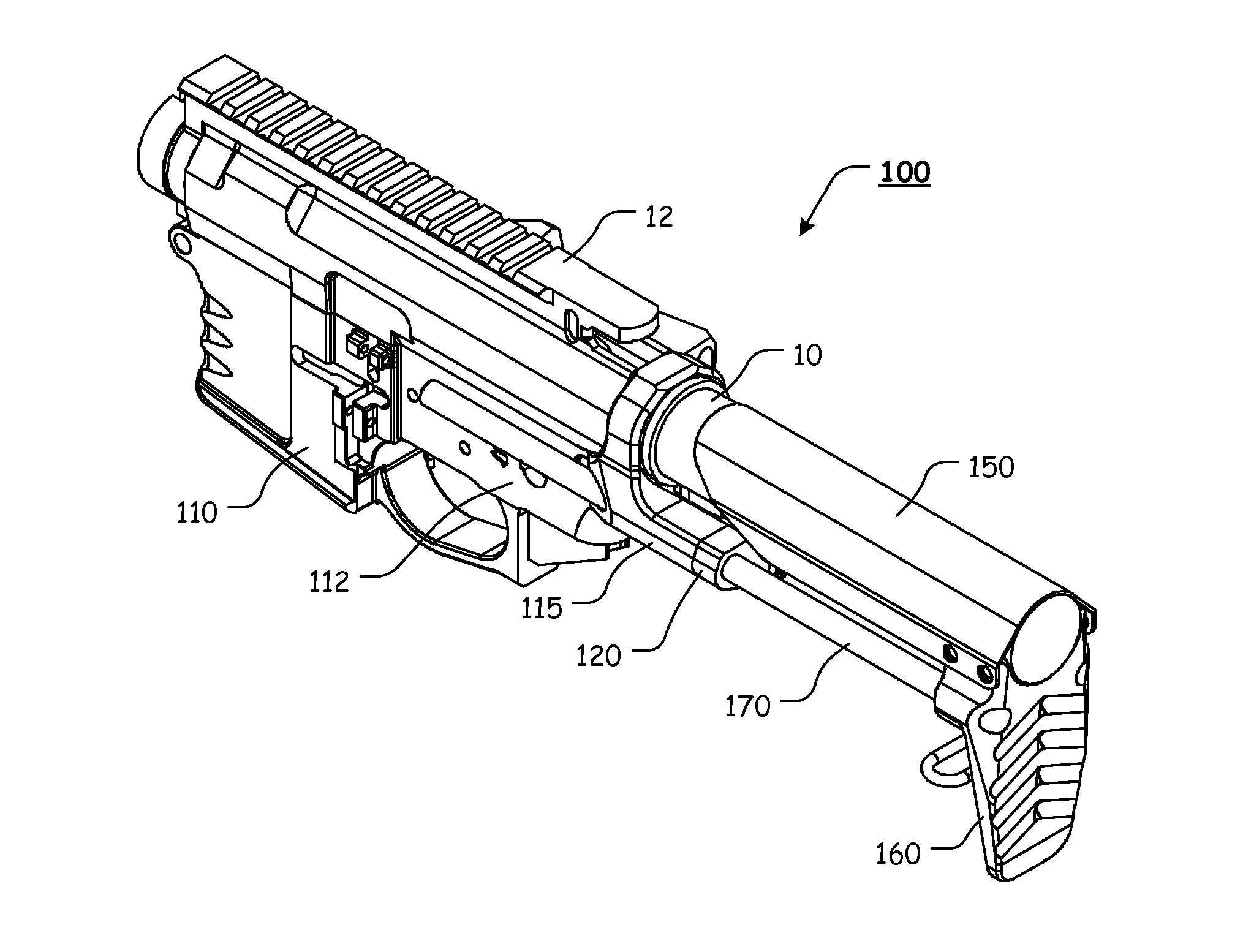
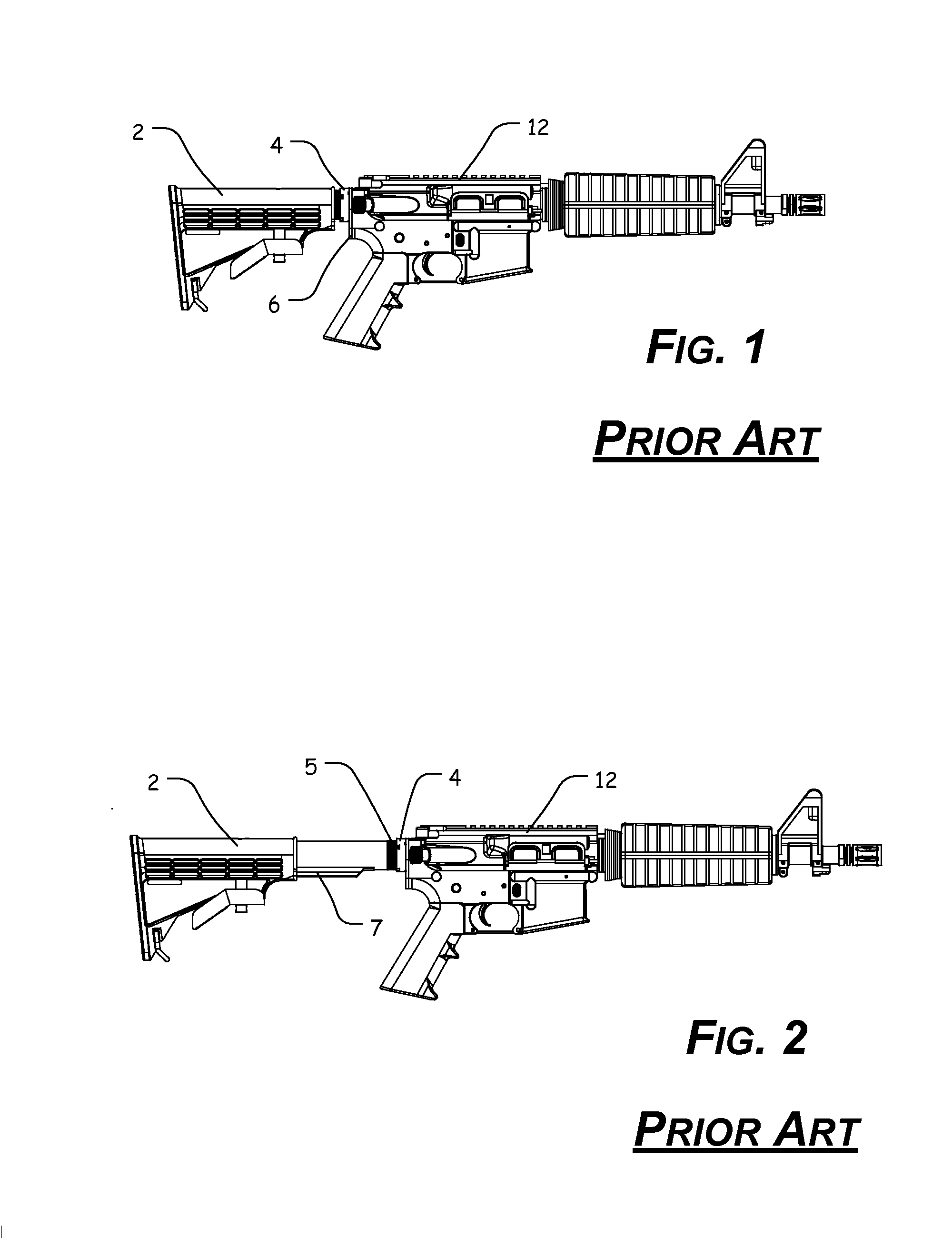
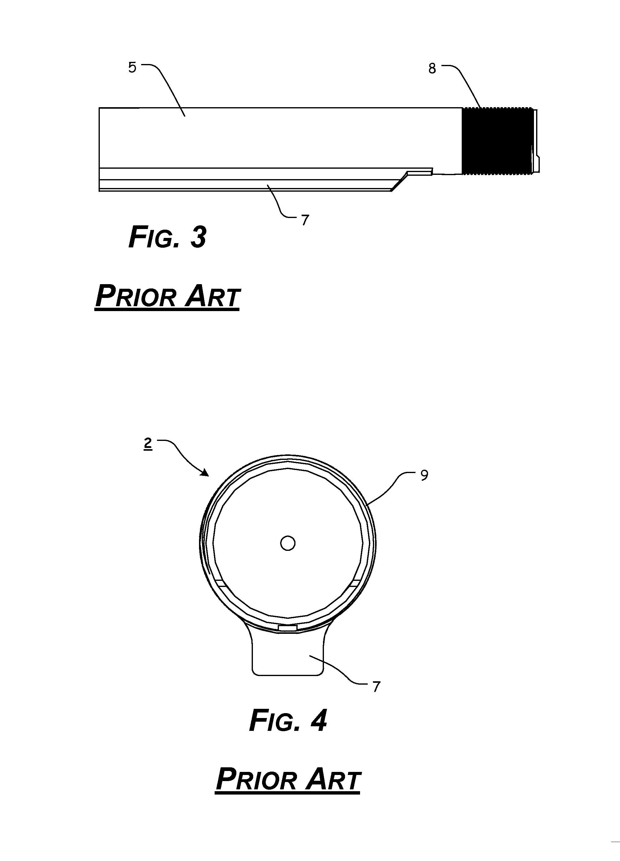
[0102]Turning now to the drawing FIGS., as discussed above, FIG. 1-4 illustrate various components of known buttstocks and buffer tubes. FIGS. 5-27 illustrate certain elements and/or aspects of a first exemplary embodiment of the receiver and collapsible buttstock 100, according to this invention. In illustrative, non-limiting embodiment(s) of this invention, as illustrated in FIGS. 5-27, the receiver and collapsible buttstock 100 comprises a receiver 110 for a firearm and an associated collapsible buttstock assembly.
[0103]As illustrated in FIGS. 5-12 and 20-21, the receiver and collapsible buttstock 100 is illustrated as including an upper receiver 12. It should be appreciated that the upper receiver 12 can be a typical upper receiver for a firearm. It should also be appreciated that a more detailed explanation of the upper receiver 12, the standard features and elements of a receiver that are not related to the present invention, the buffer tube 10, instructions regarding how to assemble the upper receiver 12, the receiver, and the buffer tube 10, and certain other items and/or techniques necessary for the implementation and/or operation of the various exemplary embodiments of the present invention are not provided herein because such elements are commercially available and/or such background information will be known to one of ordinary skill in the art. Therefore, it is believed that the level of description provided herein is sufficient to enable one of ordinary skill in the art to understand and practice the present invention, as described.
[0104]As illustrated, the receiver 110 includes an integral stock connector component 115 that extends along a portion of the receiver 110, below the buffer tube aperture. In certain exemplary, nonlimiting embodiments, the integral stock connector component 115 extends rearward, beyond the buffer tube attachment aperture of the receiver 110. However, it should be appreciated that the integral stock connector component 115 of the present invention is not so limited and may only extend as far as the buffer tube attachment aperture of the receiver 110.
[0105]Two extension rod/rail apertures 118 are formed through the integral stock connector component 115, substantially parallel to the longitudinal axis ALR of the receiver 110. In certain exemplary, nonlimiting embodiments, the extension rod/rail apertures 118 are formed outside at least a portion of the exterior wall surfaces 112 of the receiver 110. In other exemplary, nonlimiting embodiments, the extension rod/rail apertures 118 are formed at least partially within receiving channels formed in the exterior wall surfaces 112 of the receiver 110. In still other exemplary, nonlimiting embodiments, the extension rod/rail apertures 118 are formed within the integral stock connector component 115 and within the side walls of the receiver 110. Thus, the extension rod/rail apertures 118 may extend only through the integral stock connector component 115, may optionally extend through the integral stock connector component 115 and a portion of the exterior wall surfaces 112 of the receiver 110, or may optionally extend through the integral stock connector component 115 and be maintained within the side walls of the receiver 110.
[0106]The extension rod/rail apertures 118 are formed so as to slidably receive the extension rods/rails 170 that extend from the buttstock 160. In this manner, the extension rods/rails 170 are repeatably, slidably movable within the extension rod/rail apertures 118.
[0107]In certain exemplary, nonlimiting embodiments, as illustrated in FIG. 19, the extension rod/rail apertures 118 may be at least partially internally lined with a bushing or liner element 125, comprising a plastic, self-lubricating plastic, or other material to reduce friction between the interior walls of the extension rod/rail apertures 118 and the exterior surface of the extension rods/rails 170.
[0108]Additionally, gasket elements 123 may optionally be positioned between certain of the elements, such as, for example, between a rear portion of the integral stock connector component 115 and the latch cover 120 or as a cap over the latch cover 120. The gasket elements 123 may comprise a plastic, self-lubricating plastic, rubber, silicone, metal, carbon fiber, or other material. It should be appreciated that the material used to form the bushing or liner elements 125 and/or the gasket element(s) 123 is a design choice based upon the desired appearance and/or functionality of these elements.
[0109]It should also be understood that while the extension rod/rail apertures 118 (and the extension rods/rails 170) are illustrated as having a substantially circular profile, the overall shape and/or profile of the extension rod/rail apertures 118 and the extension rods/rails 170 is a design choice based upon the desired characteristics, functionality, and/or appearance of the extension rod/rail apertures 118 and the extension rods/rails 170. For example, the extension rod/rail apertures 118 and/or the extension rods/rails 170 may have a substantially circular, square, triangular, rectangular, oblong, “L” shaped, “I” shaped, “C” shaped, “V” shaped, “Z” shaped, “T” shaped, or other profile.
[0110]Furthermore, in various exemplary embodiments, the extension rods/rails 170 may be formed of a solid, hollow, or at least partially hollow portion of material.
[0111]Thus, the size and shape of the extension rod/rail apertures 118 and the extension rods/rails 170 may be altered, as desired, so long as at least a portion of the extension rods/rails 170 are able to be slidably movable within the extension rod/rail apertures 118.
[0112]As illustrated most clearly in FIGS. 22-27, the buttstock assembly comprises a buttstock 160, a cheek rest 150, and two extension rods/rails 170. The buttstock 160 comprises an elongate portion of material extending from a top end 161 to a bottom end 162. A recessed channel 165 is formed in the top end of the buttstock 160. In certain exemplary embodiments, the recessed channel 165 forms a semi-circular channel. Alternatively, the recessed channel 165 may form an alternate shape, primarily as dictated by the outer shape of the buffer tube 10.
[0113]The cheek rest 150 is formed of a substantially inverted “U” or “V” shaped portion of material that extends from a first end 151 to a second end 152. The cheek rest 150 is formed so as to be permanently or releasably attached or coupled to the buttstock 160, proximate the first end 151 of the cheek rest 150 and the top end 161 of the buttstock 160.
[0114]The cheek rest 150 is formed so as to be positioned above and at least partially around the buffer tube 10 that extends from the receiver 110. It should be appreciated that the overall size and shape of the cheek rest 150 is a design choice based upon the desired appearance and/or functionality of the cheek rest 150. Generally, the cheek rest 150 is formed so as to provide a surface for a user to position his or her cheek when the buttstock 160 is positioned against the user's shoulder. Thus, it should be understood that the exterior size and shape of the cheek rest 150 may be altered to provide a desired cheek weld for a user.
[0115]In exemplary embodiments wherein the cheek rest 150 is releasably attached or coupled to the buttstock 160, alternate shapes and sizes of cheek rest 150 can be provided such that a cheek rest 150 having a desired shape can be selected by a user.
[0116]Because of the arcuate shape of the interior of the cheek rest 150, when the cheek rest 150 is attached or coupled to the buttstock 160, the space provided between the recessed channel 165 and the cheek rest 150 defines an aperture 167, which allows the buffer tube 10 to freely slide therethrough.
[0117]FIGS. 22-25 illustrate a more detailed view of the extension rods/rails 170. In various exemplary embodiments, the extension rods/rails 170 are formed of a substantially cylindrical shaped portion of material that extends from a first end 171 to a second end 172. In various exemplary embodiments, the extension rods/rails 170 comprise a solid portion of material. Alternatively, the extension rods/rails 170 comprise a hollow or tubular portion of material.
[0118]In various exemplary, nonlimiting embodiments, a rod channel 175 is formed along at least a portion of the extension rod/rail 170. In various exemplary, nonlimiting embodiments, two or more rod dimples/detents 177 are formed along the rod channel 175. Typically, a rod dimple/detent 177 is formed at each terminating end of the rod channel 175 and one or more rod dimples/detents 177 are formed along the rod channel 175. Each extension rod/rail 170 is a mirror image of the other, such that the number and position of each rod dimple/detent 177 of each extension rod/rail 170 is aligned such that each rod dimple/detent 177 of a first extension rod/rail 170 is paired with an aligned rod dimple/detent of a second extension rod/rail 170. In this manner, each rod dimple/detent 177 represents a lockable position of the buttstock 160 relative to the receiver 110.
[0119]In certain exemplary, nonlimiting embodiments, each rod dimple/detent 177 is formed of a semi-spherical recess formed in a portion of the extension rod/rail 170. Each rod dimple/detent 177 may be formed by removing, such as, for example, by machining or cutting, material from the extension rod/rail 170. Alternatively, each rod dimple/detent 177 may be formed by pressing a rod dimple/detent 177 into the extension rod/rail 170. It should be appreciated that the rod channel 175 may be formed in a manner similar to that of the rod dimples/detents 177.
[0120]By utilizing rod dimples/detents 177 and a rod channel 175, the strength and integrity of the extension rods/rails 170 is maintained and the problems introduced by cut notches in existing collapsible stocks is circumvented. Because the majority of the strength of a rod is in the outer perimeter, by utilizing circular dimples/detents that are cut or pressed into the rod, the rod is more structurally sound than a rod having a large, flat cut across the rod.
[0121]In still other embodiments, each rod dimple/detent 177 may optionally be formed of a notch or other shaped recess formed in a portion of the extension rod/rail 170.
[0122]As illustrated in FIGS. 49A-49F, the extension rods/rails 170 may take on a number of profiles and still include structures that correspond to the rod channel 175 and the rod dimples/detents 177. For example, as illustrated in FIG. 49A, the extension rods/rails 871 has a substantially octagonal profile and includes a rod channel 875 and rod dimples/detents 877. As illustrated in FIG. 49B, the extension rods/rails 872 has a substantially triangular profile and includes a rod channel 875 and rod dimples/detents 877; as illustrated in FIG. 49C, the extension rods/rails 873 has a substantially rectangular profile and includes a rod channel 875 and rod dimples/detents 877; as illustrated in FIG. 49D, the extension rods/rails 874 has a substantially “L” shaped profile and includes a rod channel 875 and rod dimples/detents 877; as illustrated in FIG. 49E, the extension rods/rails 876 has a substantially circular, hollow profile and includes a rod channel 875 and rod dimples/detents 877; and as illustrated in FIG. 49F, the extension rods/rails 888 has a substantially C-shaped profile and includes a rod channel 875 and rod dimples/detents 877.
[0123]By utilizing one or more latch elements 140, a smooth, ball bearing-type action is provided to the lock mechanism. This system provides reduced contact surface friction and smoother and easier manipulation of the components, particularly when compared to a square/rectangular notch.
[0124]As illustrated, a first extension rod/rail 170 and a second extension rod/rail 170 are attached or coupled to the buttstock 160 so as to extend from the buttstock 160. The extension rods/rails 170 extend from the buttstock 160 so as to be aligned with and slidable within the extension rod/rail apertures 118 of the integral stock connector component 115.
[0125]As illustrated most clearly in FIGS. 17-21, the latch assembly comprises a latch cover 120, a latch 130, at least one latch element 140, and one or more latch biasing elements 145. The latch cover 120 is formed so as to be attached or coupled to the integral stock connector component 115. In various exemplary, nonlimiting embodiments, the latch cover 120 is attached or coupled to the integral stock connector component 115 via one or more screws 190. Alternatively, depending upon the materials used to create the receiver 110 and the latch cover 120, the latch cover 120 may be adhesively or otherwise permanently or removably attached to the integral stock connector component 115.
[0126]In still other exemplary, nonlimiting embodiments, the latch cover 120 may be formed as an integral component of the receiver 110.
[0127]The latch cover 120 includes interior side walls defining a latch cover cavity 122 formed so as to receive at least a portion of the latch 130 therein. The latch cover cavity 122 includes not only space for at least a portion of the latch 130, but also rod/rail apertures 124 formed therethrough. The rod/rail apertures 124 are formed so as to be aligned with the extension rod/rail apertures 118 and to slidably receive the extension rods/rails 170 that extend from the buttstock 160. In this manner, when the latch cover 120 is attached or coupled to the integral stock connector component 115, the extension rods/rails 170 are repeatably, slidably movable within the aligned rod/rail apertures 124 and the extension rod/rail apertures 118.
[0128]The latch 130 extends from an engagement portion 132 to a protrusion portion 136. An extension shoulder 134 is disposed between the engagement portion 132 and the protrusion portion 136. At least a portion of the extension shoulder 134 extends laterally, away from the longitudinal axis ALL of the latch 130, beyond a width of the engagement portion 132. At least a portion of the protrusion portion 136 extends laterally, away from the longitudinal axis ALL of the latch 130, beyond a width of the extension shoulder 134.
[0129]When the latch 130 is positioned within the latch cover cavity 122, the extension shoulder 134 interacts with side walls of the latch cover cavity 122 to maintain the latch 130 within the latch cover cavity 122. Thus, while maintained within the latch cover cavity 122, at least a portion of the engagement portion 132 protrudes from the latch cover 120 and the latch 130 is movable, along its longitudinal axis ALL. Between an engaged, or locked position, as illustrated in FIG. 20, and a disengaged or unlocked position, as illustrated in FIG. 21.
[0130]In various exemplary embodiments, a latch element 140 is positioned proximate either side of the latch cover cavity 122 and maintained between the rod/rail apertures 124 and the protrusion portions 136. In various exemplary, nonlimiting embodiments, each latch element 140 comprises a spherical ball. Alternatively, each of said latch elements 140 may comprise a cylindrical or other portion of material.
[0131]When the latch 130 is in the disengaged or unlocked position, the protrusion portions 136 are urged so as to allow the latch elements 140 to retract further into the latch cover cavity. When the latch 130 is in the engaged or locked position, the protrusion portions 136 urge the latch elements 140 into the rod/rail apertures 124.
[0132]While the latch assembly is illustrated and described as including latch element(s) 140, it should be appreciated that the latch element(s) 140 may be replaced by one or more protrusion portions, rectangular latches, or the like. Thus, it should be understood that any device, element, or feature able to be at least partially positioned within a rod channel 175 and/or rod dimples/detent 177 may be used as or in place of a latch element 140.
[0133]Additionally, while the receiver and collapsible buttstock 100 is illustrated as including two latch elements 140, it should be appreciated that the locking mechanism of the receiver and collapsible buttstock 100 may only utilize a single latch element 140, positioned proximate a single side of the latch cover cavity 122 and maintained between a single rod/rail aperture 124 and protrusion portion 136.
[0134]For example, FIGS. 44-45 illustrate an exemplary receiver and collapsible buttstock 500, which includes a receiver 510 having exterior side walls 512 and a modified integral stock connector component 515 and a modified latch cover 520. The integral stock connector component 515 and the modified latch cover 520 each include only a single rod/rail aperture. Additionally, only a single extension rod/rail 170 extends from the buttstock 560.
[0135]One or more biasing element receiving recesses 138 may optionally be formed within an upper portion of the latch 130. The biasing element receiving recess(es) 138 allow one or more latch biasing elements 145 to be at least partially positioned therein so as to maintain alignment of the latch biasing elements 145 between the latch 130 and the interior of the latch cover cavity 122.
[0136]In various exemplary embodiments, the biasing elements 145 comprise a spring. Alternatively, the biasing element(s) 145 may comprise a single spring or multiple springs, a leaf spring, a resilient portion of material, such as, for example, rubber or silicone, or any other mechanism that can store and return energy in a fashion similar to that of a spring.
[0137]In still other exemplary embodiments, as illustrated in FIGS. 47 and 48, the spring biasing element(s) 145 may optionally be replaced with a spring biasing element 645, such as, for example, a bent piece of spring steel or leaf spring. Alternatively, the spring biasing element(s) 145 may optionally be replaced with a spring biasing element 745, such as, for example, a resilient block or portion of material.
[0138]In certain of these exemplary embodiments, as illustrated, the one or more biasing element receiving recesses 138 are removed from the latch 130.
[0139]The biasing elements 145 are positioned between the latch 130 and an interior surface of the latch cover cavity 122, so as to bias the latch 130 to the engaged or locked position, as illustrated in FIG. 20.
[0140]The interaction between the latch elements 140 and the rod/rail apertures 124 is such that when the latch 130 is in the disengaged or unlocked position, the latch elements 140 are retracted so as to travel within the rod channels 175 of the extension rods/rails 170. However, while in the disengaged or unlocked position, the latch 130 limits the retraction of the latch elements 140 within the latch cover cavity 122 such that the latch elements 140 protrude into the rod/rail apertures 124 a sufficient distance to be maintained within the rod channel 175, thereby limiting the slidable movement of the extension rods/rails 170 (and the cheek rest 150 and buttstock 160) relative to the receiver 110.
[0141]In the engaged or locked position, the latch 130 urges the latch elements 140 further into the rod/rail apertures 124, thereby maintaining each latch element 140 within a rod dimple/detent 177.
[0142]Thus, through interaction of the latch elements 140 and the rod dimples/detents 177, the buttstock assembly can be releasably secured at a desired position relative to the receiver 110.
[0143]In various exemplary embodiments, various components of the receiver and collapsible buttstock 100 are substantially rigid and are formed of aluminum. Alternate materials of construction of the various components of the receiver and collapsible buttstock 100 may include one or more of the following: steel, stainless steel, titanium, and/or other metals, as well as various alloys and composites thereof, glass-hardened polymers, polymeric composites, polymer or fiber reinforced metals, carbon fiber or glass fiber composites, continuous fibers in combination with thermoset and thermoplastic resins, chopped glass or carbon fibers used for injection molding compounds, laminate glass or carbon fiber, epoxy laminates, woven glass fiber laminates, impregnate fibers, polyester resins, epoxy resins, phenolic resins, polyimide resins, cyanate resins, high-strength plastics, nylon, glass, or polymer fiber reinforced plastics, thermoform and/or thermoset materials, and/or various combinations of the foregoing. Thus, it should be understood that the material or materials used to form the various components of the receiver and collapsible buttstock 100 is a design choice based on the desired appearance and functionality of the receiver and collapsible buttstock 100.
[0144]It should be appreciated that certain elements of the receiver and collapsible buttstock 100 may be formed as an integral unit (such as, for example, the buttstock 160 and the extension rods/rails 170). Alternatively, suitable materials can be used and sections or elements made independently and attached or coupled together, such as by adhesives, welding, screws, rivets, pins, or other fasteners, to form the various elements of the receiver and collapsible buttstock 100.
[0145]It should also be understood that the overall size and shape of the receiver and collapsible buttstock 100, and the various portions thereof, is a design choice based upon the desired functionality and/or appearance of the receiver and collapsible buttstock 100.
[0146]During use, the buttstock assembly may initially be presented in a retracted or collapsed position, as illustrated in FIG. 9. In this position, the latch 130 is in the engaged or locked position and the latch elements 140 are positioned within the rod dimples/detents 177 formed at a first terminal end 178 of the rod channel 175. The interaction of the protrusion portions 136, the latch elements 140, and the rod dimples/detents 177 is sufficient to maintain the buttstock assembly in the collapsed or retracted position even if a withdrawing force is applied to the buttstock assembly.
[0147]When a user desires to extend the buttstock assembly, the user merely urges the latch 130 upward, along the longitudinal axis ALL, to the disengaged or unlocked position. Because of the convenient position of the engagement portion 132 of the latch 130, intentional manipulation of the latch 130 can be accomplished easily, with the user's finger, thumb, or another surface.
[0148]As the latch 130 is urged toward the disengaged or unlocked position, the protrusion portions 136 allow the latch elements 140 to retract into the latch cover cavity 122 a sufficient distance so as to be removed from the rod dimples/detents 177 but maintained within the rod channel 175. Thus, the extension rods/rails 170 can be slidably withdrawn from the rod/rail apertures 124 and the extension rail apertures 118, a distance permitted by the length of the rod channel 175 and the rod dimple/detent positioned at the second terminal end 179 of the rod channel 175.
[0149]In certain exemplary, nonlimiting embodiments, the distance from the first terminal end 178 of the rod channel 175 to the second terminal end 179 of the rod channel 175 is approximately 3 inches. Alternatively, the distance from the terminal ends may be greater or less than 3 inches and may be, for example, 2-10 inches or more.
[0150]When the user no longer urges the latch 130 to the unlocked or disengaged position, the spring bias of the latch biasing elements 145 urges the latch 130 toward the engaged or locked position, such that the latch elements 140 may continue to allow slidable movement of the extension rods/rails 170 until the latch elements 140 reach a rod dimple/detent 177. Upon reaching a rod dimple/detent 177, the spring biasing force of the latch biasing elements 145 urges the latch elements 140 into the rod dimples/detents 177, thereby locking the buttstock assembly into a given position relative to the receiver 110.
[0151]FIGS. 28-29 illustrate a second exemplary embodiment of a receiver and collapsible buttstock 200 being assembled together with an upper receiver 12 and buffer tube 10. FIG. 28 illustrates the buttstock assembly in a fully collapsed position, while FIG. 29 illustrates the buttstock assembly in a fully extended position.
[0152]As shown in FIGS. 28-29, the receiver and collapsible buttstock 200 comprises elements similar to those of the receiver and collapsible buttstock 100. However, as shown in FIGS. 28-29, the receiver 100 is replaced by the receiver 210. Receiver 210 includes an integral stock connector component 215 that extends rearward, as far as the buffer tube attachment aperture of the receiver 210. Thus, the integral stock connector component 215 does not extend as far rearward as the integral stock connector component 115.
[0153]Additionally, the integral stock connector component 215 extends along a greater portion of the receiver 210 (and the exterior wall surfaces 212 of the receiver 210) than the integral stock connector component 115 extends along the receiver 110.
[0154]FIGS. 30-31 illustrate a third exemplary embodiment of a receiver and collapsible buttstock 300 being assembled together with an upper receiver 12 and buffer tube 10.
[0155]As shown in FIGS. 30-31, the receiver and collapsible buttstock 300 comprises elements similar to those of the receiver and collapsible buttstock 100 and/or 200. However, as shown in FIGS. 30-31, the receiver 100 and/or 200 is replaced by receiver 310. The receiver 310 includes an integral stock connector component 315 that is formed higher up on the receiver 310 when compared to the location of the integral stock connector components 115 and 215.
[0156]The integral stock connector component 315 is positioned such that the extension rod/rail apertures 318 are formed outside at least a portion of the exterior wall surfaces 312 of the receiver 310, along either side of the buffer tube aperture. Thus, when assembled, the extension rods/rails 170 are located substantially alongside and coplanar to the buffer tube 10.
[0157]In this manner, the extension rods/rails 170 are aligned along either side of the bore axis of the receiver, causing the majority of recoil experienced during firing of the rifle to be directed in a substantially straight line back from the receiver, through the extension rods/rails 170, to the buttstock 160. By directing the recoil straight back, along the bore axis and along substantially coplanar components, the amount of muscle rise experienced during firing is reduced, when compared to conventional collapsible stock assemblies.
[0158]As illustrated most clearly in FIG. 30, the forward assist that is typically included on an upper receiver 12 is removed so as to allow the extension rod/rail 170, located on the right side of the receiver 12 to move along the right side of the receiver 12. In certain exemplary, nonlimiting embodiments, a recess is formed in the shell deflector of the upper receiver 12 to act as an additional stop for the extension rod/rail 170 located on the right side of the receiver 12.
[0159]FIGS. 32-44 illustrate various views of a view of an exemplary embodiment of a receiver and collapsible buttstock 400 and an upper receiver 480, according to this invention. As shown in FIGS. 32-44, the receiver and collapsible buttstock 400 comprises at least some of a lower receiver 410, an upper receiver 480, a buffer tube 10, extension rod/rails 470, and a buttstock 460.
[0160]It should be understood that the buffer tube 10, the extension rod/rails 470, and the buttstock 460 correspond generally to and operates similarly to the buffer tube 10, the extension rod/rails 170, and the buttstock 160, as described above with reference to the receiver and collapsible buttstock 100 of FIGS. 5-27.
[0161]However, as shown in FIGS. 32-44, the lower receiver 410 can be a typical for a firearm, known lower receiver. It should be appreciated that a more detailed explanation of the lower receiver 410, the standard features and elements of a lower receiver that are not related to the present invention, the buffer tube 10, instructions regarding how to assemble the upper receiver 480, the lower receiver 410, and the buffer tube 10, and certain other items and/or techniques necessary for the implementation and/or operation of the various exemplary embodiments of the present invention are not provided herein because such elements are commercially available and/or such background information will be known to one of ordinary skill in the art. Therefore, it is believed that the level of description provided herein is sufficient to enable one of ordinary skill in the art to understand and practice the present invention, as described.
[0162]As illustrated, the upper receiver 480 includes an integral stock connector component 415 that extends along a portion of the upper receiver 480, proximate either side of the buffer tube aperture. In certain exemplary, nonlimiting embodiments, the integral stock connector component 415 extends along the side walls of the upper receiver 480. Depending on the length of the stock connector component 415 formed on the right side of the upper receiver 480, the integral stock connector component 415 may replace the forward assist and/or the shell deflector of the right side of the upper receiver 480.
[0163]Two extension rod/rail apertures 488 are formed through the integral stock connector component 415, substantially parallel to the longitudinal axis ALR of the upper receiver 480. In certain exemplary, nonlimiting embodiments, the extension rod/rail apertures 488 are formed outside at least a portion of the exterior wall surfaces 487 of the upper receiver 480. In other exemplary, nonlimiting embodiments, the extension rod/rail apertures 488 may be formed at least partially within receiving channels formed in the exterior wall surfaces 487 of the upper receiver 480. In still other exemplary, nonlimiting embodiments, the extension rod/rail apertures 488 are formed within the integral stock connector component 415 and within the side walls of the upper receiver 480. Thus, the extension rod/rail apertures 488 may extend only through the integral stock connector component 415, may optionally extend through the integral stock connector component 415 and a portion of the exterior wall surfaces 487 of the upper receiver 480, or may optionally extend through the integral stock connector component 415 and be maintained within the side walls of the upper receiver 480.
[0164]The extension rod/rail apertures 488 are formed so as to slidably receive the extension rods/rails 470 that extend from the buttstock 460. In this manner, the extension rods/rails 470 are repeatably, slidably movable within the extension rod/rail apertures 488.
[0165]In certain exemplary, nonlimiting embodiments, the extension rod/rail apertures 488 may be at least partially internally lined with a bushing or liner element, comprising a plastic, self-lubricating plastic, or other material to reduce friction between the interior walls of the extension rod/rail apertures 488 and the exterior surface of the extension rods/rails 470.
[0166]It should also be understood that while the extension rod/rail apertures 488 (and the extension rods/rails 470) are illustrated as having a substantially circular profile, the overall shape and/or profile of the extension rod/rail apertures 488 and the extension rods/rails 470 is a design choice based upon the desired characteristics, functionality, and/or appearance of the extension rod/rail apertures 488 and the extension rods/rails 470. For example, the extension rod/rail apertures 488 and/or the extension rods/rails 470 may have a substantially circular, square, triangular, rectangular, oblong, “L” shaped, “I” shaped, “C” shaped, “V” shaped, “Z” shaped, “T” shaped, or other profile.
[0167]Furthermore, in various exemplary embodiments, the extension rods/rails 470 may be formed of a solid, hollow, or at least partially hollow portion of material.
[0168]Thus, the size and shape of the extension rod/rail apertures 488 and the extension rods/rails 470 may be altered, as desired, so long as at least a portion of the extension rods/rails 470 are able to be slidably movable within the extension rod/rail apertures 488.
[0169]As illustrated most clearly in FIGS. 39-42, the buttstock assembly comprises a buttstock 460 and two extension rods/rails 470. The buttstock 460 comprises an elongate portion of material extending from a top end 461 to a bottom end 462. A recessed channel 465 is formed in the top end of the buttstock 460. In certain exemplary embodiments, the recessed channel 465 forms an arcuate or semi-circular channel. Alternatively, the recessed channel 465 may form an alternate shape, primarily as dictated by the outer shape of the buffer tube 10.
[0170]Because of the arcuate or semi-circular shape of the recessed channel 465, the space provided within the recessed channel 465 defines an area within the buttstock 460, which allows the buffer tube 10 to freely slide therethrough.
[0171]In certain exemplary, nonlimiting embodiments, a cheek rest (not illustrated) may be permanently or releasably attached or coupled to the buttstock 460.
[0172]In various exemplary embodiments, the extension rods/rails 470 are formed of a substantially cylindrical shaped portion of material that extends from a first end to a second end. In various exemplary embodiments, the extension rods/rails 470 comprise a solid portion of material. Alternatively, the extension rods/rails 470 comprise a hollow or tubular portion of material.
[0173]In various exemplary, nonlimiting embodiments, two or more rod dimples/detents are formed along the rod channel. The rod channel and rod dimples/detents correspond to and operate similarly to the rod channel 175 and the rod dimples/detents 177, as described above with respect to the receiver and collapsible buttstock 100.
[0174]As illustrated, a first extension rod/rail 470 and a second extension rod/rail 470 are attached or coupled to the buttstock 460 so as to extend from the buttstock 460. The extension rods/rails 470 extend from the buttstock 460 so as to be aligned with and slidable within the extension rod/rail apertures 488 of the integral stock connector component 415.
[0175]The integral stock connector component 415 is positioned such that the extension rod/rail apertures 418 are formed outside at least a portion of the exterior wall surfaces 412 of the receiver 410, along either side of the buffer tube aperture. Thus, when assembled, the extension rods/rails 170 are located substantially alongside and coplanar to the buffer tube 10.
[0176]In this manner, the extension rods/rails 170 are aligned along either side of the bore axis of the receiver, causing the majority of recoil experienced during firing of the rifle to be directed in a substantially straight line back from the receiver, through the extension rod/rails 170, to the buttstock 160. By directing the recoil straight back, along the bore axis and along substantially coplanar components, the amount of muscle rise experienced during firing is reduced, when compared to conventional collapsible stock assemblies.
[0177]As illustrated most clearly in FIGS. 33, 35, 40, 41, and 44, the latch assembly comprises a latch 430 pivotably attached or coupled, via a pivot pin 435, within a latch cavity 482. The latch 430 comprises a finger button end and an engagement end and is pivotable, via the pivot pin 435, between an engaged and a disengaged position. Typically, the finger button end is divided from the engagement end proximate the pivot point.
[0178]The latch cavity 482 provides a recessed area for the latch 430. An aperture 483 is provided proximate the engagement end of the latch cavity 482, which provides access between the latch cavity 482 and the interior of the extension rod/rail aperture 488 below the latch cavity 482.
[0179]The latch 430 is typically spring biased, via a biasing element, to the engaged position. In the engaged position, a protrusion from the latch 430 protrudes through the latch cavity 482 and into the extension rod/rail aperture 488 a sufficient distance to engage and be at least partially positioned within a rod channel 475 and/or rod dimples/detent 477.
[0180]When the latch 430 is pivoted to the disengaged or unlocked position, via urging of the finger button end, the protrusion is withdrawn a sufficient distance from the extension rod/rail aperture 488 to disengage from the rod dimples/detent 477, but continue to be maintained within the rod channel 475.
[0181]Thus, through interaction of the protrusion of the latch 430 and the rod dimples/detents 477, the buttstock assembly can be releasably secured at a desired position relative to the upper receiver 480.
[0182]While the receiver and collapsible buttstock 400 is illustrated as including a single latch 430 maintained within a latch cavity 482 formed on the right side of the upper receiver 480, it should be appreciated that an additional latch 430 may be included within a latch cavity 482 formed on the left side of the upper receiver 480.
[0183]In various exemplary embodiments, various components of the receiver and collapsible buttstock 400 are substantially rigid and are formed of aluminum. Alternate materials of construction of the various components of the receiver and collapsible buttstock 400 may include one or more of the following: steel, stainless steel, titanium, and/or other metals, as well as various alloys and composites thereof, glass-hardened polymers, polymeric composites, polymer or fiber reinforced metals, carbon fiber or glass fiber composites, continuous fibers in combination with thermoset and thermoplastic resins, chopped glass or carbon fibers used for injection molding compounds, laminate glass or carbon fiber, epoxy laminates, woven glass fiber laminates, impregnate fibers, polyester resins, epoxy resins, phenolic resins, polyimide resins, cyanate resins, high-strength plastics, nylon, glass, or polymer fiber reinforced plastics, thermoform and/or thermoset materials, and/or various combinations of the foregoing. Thus, it should be understood that the material or materials used to form the various components of the receiver and collapsible buttstock 400 is a design choice based on the desired appearance and functionality of the receiver and collapsible buttstock 400.
[0184]It should be appreciated that certain elements of the receiver and collapsible buttstock 400 may be formed as an integral unit (such as, for example, the buttstock 460 and the extension rods/rails 470). Alternatively, suitable materials can be used and sections or elements made independently and attached or coupled together, such as by adhesives, welding, screws, rivets, pins, or other fasteners, to form the various elements of the receiver and collapsible buttstock 400.
[0185]It should also be understood that the overall size and shape of the receiver and collapsible buttstock 400, and the various portions thereof, is a design choice based upon the desired functionality and/or appearance of the receiver and collapsible buttstock 400.
[0186]While the receiver and collapsible buttstock 400 is illustrated and described as having two extension rods/rails 470 engaging two extension rod/rail apertures 488, it should be appreciated that the receiver and collapsible buttstock 400 may include a single extension rod/rail 470 engaging a single extension rod/rail aperture 488.
[0187]During use, the buttstock assembly may initially be presented in a retracted or collapsed position, as illustrated in FIGS. 39-44. In this position, the latch 430 is in the engaged or locked position and the protrusion portion of the latch 430 is positioned within the rod dimples/detents formed at a first terminal end 478 of the rod channel 475. The interaction of the protrusion portion protrusion portion of the latch 430, and the rod dimples/detents is sufficient to maintain the buttstock assembly in the collapsed or retracted position even if a withdrawing force is applied to the buttstock assembly.
[0188]When a user desires to extend the buttstock assembly, the user merely engages the finger button portion of the latch 430 and urges the finger button portion inward, to the disengaged or unlocked position. Because the latch 430 is at least partially positioned within the latch cavity 482, unintentional manipulation of the latch 430 can be avoided.
[0189]As the latch 430 is pivotably urged toward the disengaged or unlocked position, the protrusion portion of the latch 430 is withdrawn from the extension rods/rail aperture 488 a sufficient distance so as to be removed from the rod dimples/detents but maintained within the rod channel 475. Thus, the extension rods/rails 470 can be slidably withdrawn from the extension rail apertures 488, a distance permitted by the length of the rod channel and the rod dimple/detent positioned at the second terminal end 479 of the rod channel 475.
[0190]In certain exemplary, nonlimiting embodiments, the distance from the first terminal end 478 of the rod channel to the second terminal end 479 of the rod channel is approximately 3 inches. Alternatively, the distance from the terminal ends may be greater or less than 3 inches and may be, for example, 2-10 inches or more.
[0191]When the user no longer urges the latch 430 to the unlocked or disengaged position, the spring bias of the latch biasing elements urges the latch 430 toward the engaged or locked position, such that the protrusion portion of the latch 430 may continue to allow slidable movement of the extension rods/rails 470 until the protrusion portion of the latch 430 reaches a rod dimple/detent 477. Upon reaching a rod dimple/detent477, the spring biasing force of the latch biasing element urges the protrusion portion of the latch 430 into the rod dimples/detents 477, thereby locking the buttstock assembly into a given position relative to the upper receiver 480.
[0192]While this invention has been described in conjunction with the exemplary embodiments outlined above, the foregoing description of exemplary embodiments of the invention, as set forth above, are intended to be illustrative, not limiting and the fundamental invention should not be considered to be necessarily so constrained. It is evident that the invention is not limited to the particular variation set forth and many alternatives, adaptations modifications, and/or variations will be apparent to those skilled in the art.
[0193]Furthermore, where a range of values is provided, it is understood that every intervening value, between the upper and lower limit of that range and any other stated or intervening value in that stated range is encompassed within the invention. The upper and lower limits of these smaller ranges may independently be included in the smaller ranges and is also encompassed within the invention, subject to any specifically excluded limit in the stated range. Where the stated range includes one or both of the limits, ranges excluding either or both of those included limits are also included in the invention.
[0194]It is to be understood that the phraseology of terminology employed herein is for the purpose of description and not of limitation. Unless defined otherwise, all technical and scientific terms used herein have the same meaning as commonly understood by one of ordinary skill in the art to which this invention belongs.
[0195]In addition, it is contemplated that any optional feature of the inventive variations described herein may be set forth and claimed independently, or in combination with any one or more of the features described herein.
[0196]Accordingly, the foregoing description of exemplary embodiments will reveal the general nature of the invention, such that others may, by applying current knowledge, change, vary, modify, and/or adapt these exemplary, non-limiting embodiments for various applications without departing from the spirit and scope of the invention and elements or methods similar or equivalent to those described herein can be used in practicing the present invention. Any and all such changes, variations, modifications, and/or adaptations should and are intended to be comprehended within the meaning and range of equivalents of the disclosed exemplary embodiments and may be substituted without departing from the true spirit and scope of the invention.
[0197]Also, it is noted that as used herein and in the appended claims, the singular forms “a”, “and”, “said”, and “the” include plural referents unless the context clearly dictates otherwise. Conversely, it is contemplated that the claims may be so-drafted to require singular elements or exclude any optional element indicated to be so here in the text or drawings. This statement is intended to serve as antecedent basis for use of such exclusive terminology as “solely”, “only”, and the like in connection with the recitation of claim elements or the use of a “negative” claim limitation(s).

PUM

no PUM

Description & Claims & Application Information

We can also present the details of the Description, Claims and Application information to help users get a comprehensive understanding of the technical details of the patent, such as background art, summary of invention, brief description of drawings, description of embodiments, and other original content. On the other hand, users can also determine the specific scope of protection of the technology through the list of claims; as well as understand the changes in the life cycle of the technology with the presentation of the patent timeline. Login to view more.

Similar technology patents

High temperature hot delivery steel billet transportation special vehicle side wall

PendingCN107187453AIncreased Strength and RigidityImprove the ability to resist foreign inflation
Owner:CRRC MEISHAN

Technology for manufacturing diesel engine cast steel intermediate

InactiveCN108927492AImprove physical performanceIncreased Strength and Rigidity
Owner:全椒县全动机械有限公司

Automobile doorsill

ActiveCN102874322BIncreased Strength and RigidityReduce the difficulty of spraying
Owner:CHERY COMML VEHICLE ANHUI

Classification and recommendation of technical efficacy words

  • increased strength and rigidity
  • easily manipulate

Modified composite material with recovered polypropylene as matrix and preparation method thereof

ActiveCN103254500AIncreased Strength and RigidityImprove abrasion and impact resistance
Owner:CGN JUNER NEW MATERIALS +1

Surfboard having a skin of reinforced fabric

InactiveUS20070218787A1increased strength and rigidity
Owner:JPS COMPOSITE MATERIALS

Battery box and manufacture method thereof

Owner:惠州市海龙新材料科技有限公司

Cutting reducer for roadheader

Owner:DALIAN HUARUI HEAVY IND GROUP

Metal-bonded diamond grinding wheel

InactiveCN104985536AIncreased Strength and RigidityImprove heat resistance and heat dissipation performance
Owner:蓬莱市超硬复合材料有限公司

Articulating radio frequency probe handle

InactiveUS7087051B2easily manipulate
Owner:BOSTON SCI SCIMED INC

Method and apparatus for acquiring blood for testing

InactiveUS20130116597A1easily manipulate
Owner:NEOTERYX

Rolling pastry cutter kit with interchangeable pastry cutting units and method of use thereof

InactiveUS20050153023A1easily manipulatereadily remove
Owner:OVERTON COREY DAVID

Device and method for sheathing a lock of hair

InactiveUS20070068547A1easily manipulate
Owner:THE PROCTER & GAMBNE CO

Motivational toy for a pet

ActiveUS20130025543A1improve transporteasily manipulate
Owner:THE KYJEN CO LLC +1
Why Eureka
Try Eureka