System for uniformly illuminating target to reduce speckling

a target and uniform illumination technology, applied in the field of lasers, can solve the problems of residual non-uniform background illumination and unintended disturbances of the endoscopic system, and achieve the effect of facilitating uniform illumination and facilitating target imaging

Active Publication Date: 2016-09-08
BAE SYST INFORMATION & ELECTRONICS SYST INTERGRATION INC
View PDF9 Cites 1 Cited by
  • Summary
  • Abstract
  • Description
  • Claims
  • Application Information

AI Technical Summary

Benefits of technology

[0008]The present invention provides an apparatus which uniformly illuminates a desired target by use of at least one laser, such as a laser diode, to facilitate imaging of the target by a conventional imaging system, such as a camera. The invention utilizes many independent, or quasi-independent, point sources of light and also comprises at least one laser source, a multi-fiber or fiber optic bundle, and typically an oscillating diffuser which assists with scrambling the light prior to illumination of the target. The present invention also minimizes the associated cost of adequately illuminating the target while simultaneously greatly reducing the speckle effect of an image of the target.
[0015]The present invention further relates to a method of uniform illumination of a target, by an illumination system, to facilitate imaging of the target by an imaging system, the apparatus comprising: generating a plurality of independent or quasi-independent point sources of light via a laser source; forming a fiber optic bundle comprising a plurality of individual optical fibers for each receiving at least one of the plurality of point sources of light, from the laser source, and directing the plurality of point sources of light toward the target for illumination thereof; and receiving the plurality of point sources of light, via an oscillating diffuser, and oscillating the oscillating diffuser at a frequency so as to redirect each one of the plurality of point sources of light over an area of the target to be illuminated to facilitate uniform illumination and imaging thereof.

Problems solved by technology

Further limitations of this apparatus include image distortion due to residual non-uniform background illumination.
However, transmission of motor vibrations onto the housing or other components of the proximal supply unit can cause unintended disturbances of the endoscopic system.

Method used


Image

  • System for uniformly illuminating target to reduce speckling
  • System for uniformly illuminating target to reduce speckling
  • System for uniformly illuminating target to reduce speckling

Examples


Embodiment Construction

[0026]The present invention will be understood by reference to the following detailed description, which should be read in conjunction with the appended drawings. It is to be appreciated that the following detailed description of various embodiments is by way of example only and is not meant to limit, in any way, the scope of the present invention.

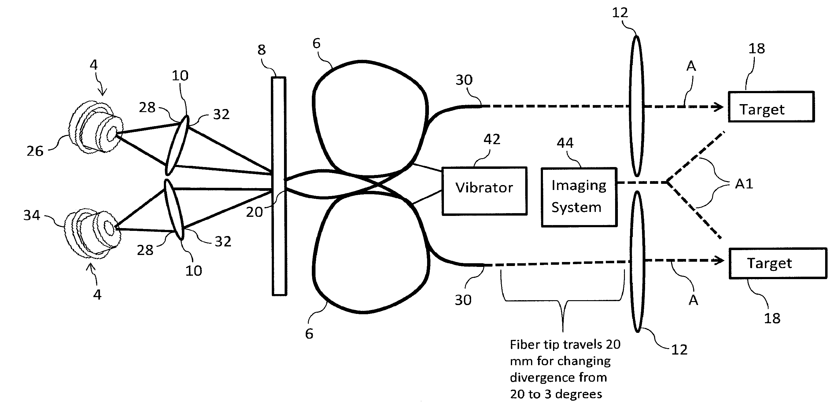
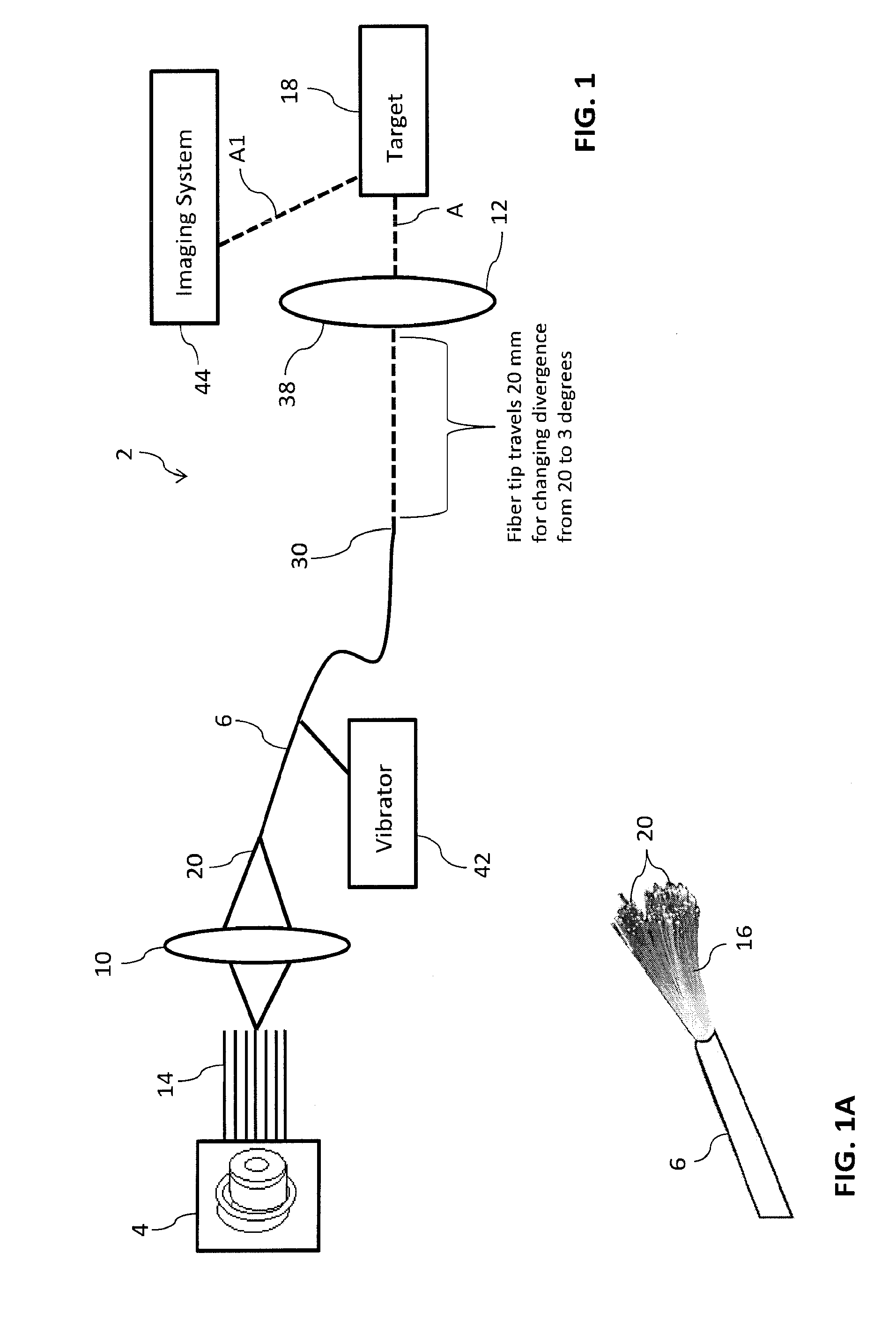
[0027]As briefly noted above, prior attempts at reducing speckle were costly and did not adequately achieve an speckle reduction. Previously, a diverter would be used to randomize the light and such arrangement typically required optical fiber length between 10-20 meters in order to reduce speckle contained in the image of the illuminated target. The present invention allows for a much shorter distance of optical fiber cable in order to sufficiently reduce the speckle effect contained within an image of the illuminated target. As described more fully herein and the accompanying figures and the following description, the present invention p...


PUM


Abstract

An illumination system for uniform illumination of a target to facilitate imaging of the target by an imaging system. The apparatus which comprises a laser source for generating a plurality of independent or quasi-independent point sources of light; a fiber optic bundle which comprises a plurality of individual optical fibers for each receiving at least one of the plurality of point sources of light, from the laser source, and directing the plurality of point sources of light toward the target for illumination thereof; and an oscillating diffuser for receiving the plurality of point sources of light and oscillating at a frequency so as to redirect each one of the plurality of point sources of light over an area of the target to be illuminated to facilitate uniform illumination and imaging thereof.

Description

FIELD OF THE INVENTION[0001]The present invention relates to lasers and, more particularly, the invention relates to using at least one laser in order to uniformly illuminate a desired target and facilitate improved imaging of the target by a conventional imaging device or system.BACKGROUND OF THE INVENTION[0002]The prior art discloses a number of ways to achieve desired illumination of a target.[0003]For example, U.S. Pat. No. 6,672,739 concerns a laser beam homogenizer. This apparatus was developed for the illumination of lithographic masks, or more specifically, an object in a microscope. The output of a laser beam homogenizer is imaged onto a field for wide field illumination. The image of the output is dithered with respect to the field. However, this apparatus requires that the illuminating ray bundle must be injected into the lens along a plane defined by one of the great arcs on the lens surface and the light polarization must be parallel- or perpendicular to that plane. Fur...

Claims


Application Information

Patent Timeline
Patent Type & Authority Applications(United States)
IPC IPC(8): G02B27/48G02B6/04G03B15/06G02B26/08
CPCG02B27/48G03B15/06G02B6/04G02B26/08G02B6/06G02B21/0028
Inventor CHOINIERE, MICHAEL J.
Owner BAE SYST INFORMATION & ELECTRONICS SYST INTERGRATION INC
Why Eureka
Try Eureka