Antenna device of base station

a technology of antenna unit and base station, which is applied in the direction of antennas, antenna details, basic electric elements, etc., can solve the problems of increasing rental costs and increasing installation costs, and achieve the effect of reducing maintenance costs and minimizing installation costs of antenna units

Inactive Publication Date: 2016-09-08
KMW INC
View PDF0 Cites 49 Cited by
  • Summary
  • Abstract
  • Description
  • Claims
  • Application Information

AI Technical Summary

Benefits of technology

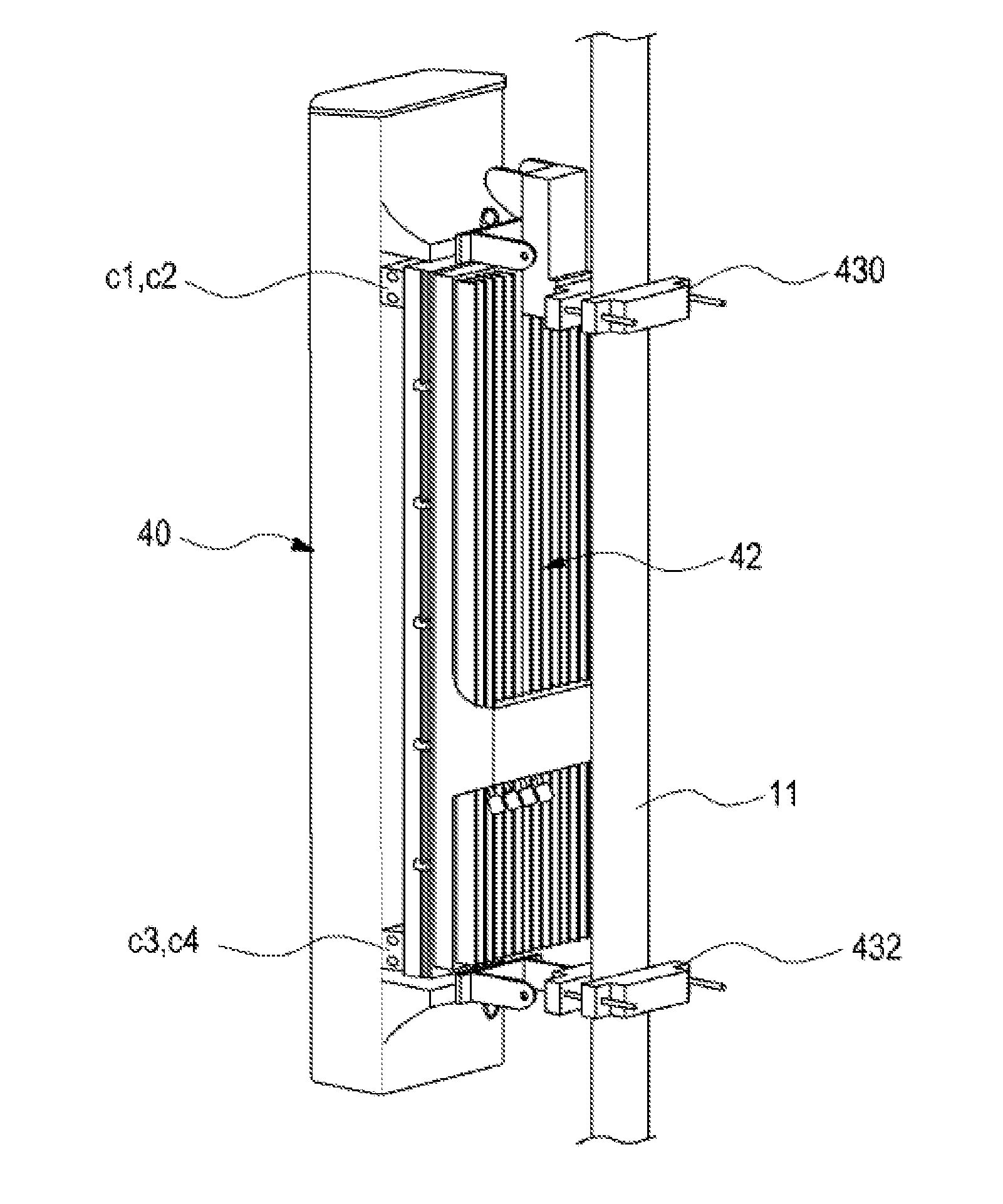
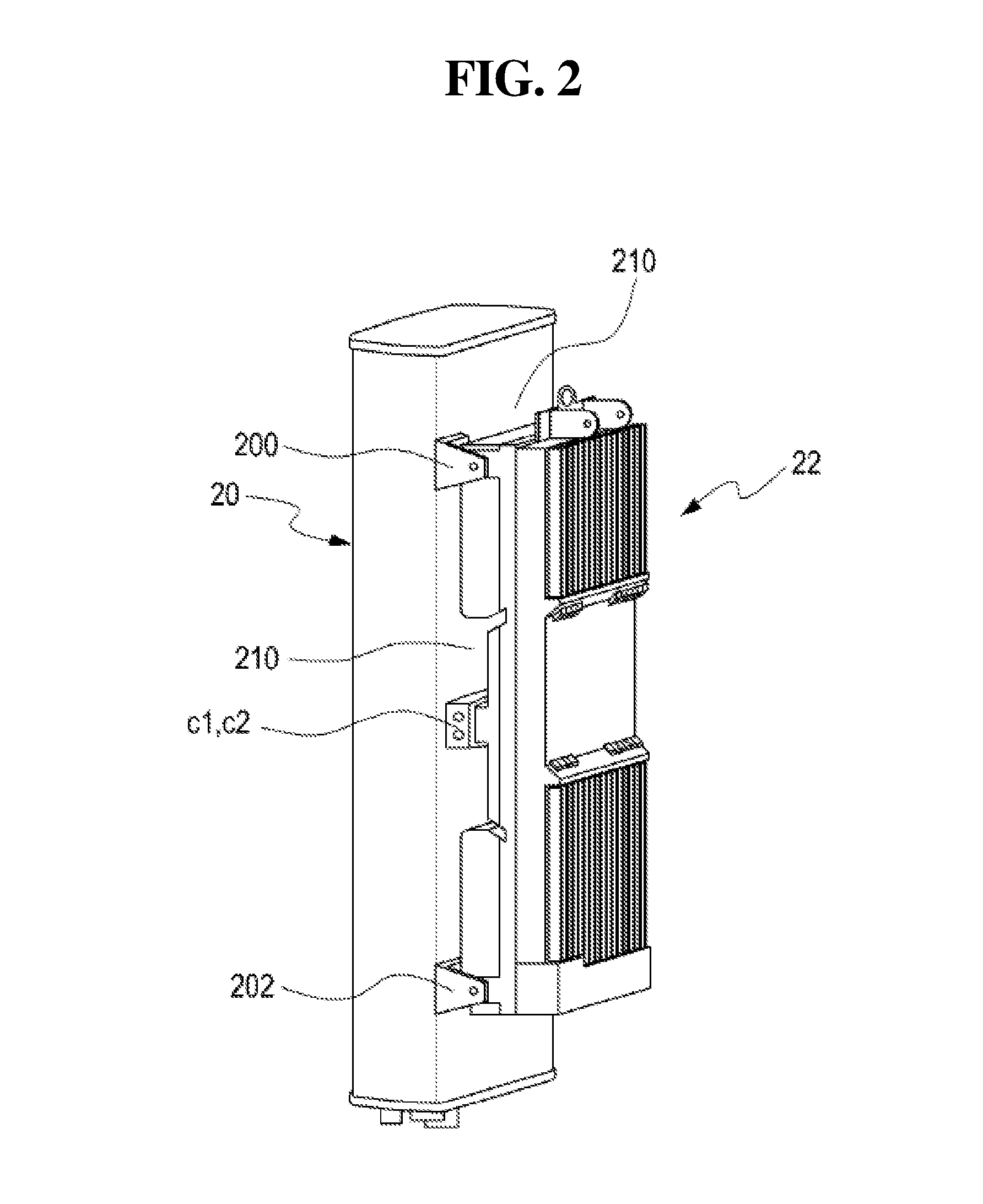
[0009]Various embodiments of the present disclosure are to provide an antenna unit for a base station in which components used for installing an antenna module and a repeater are minimized so that installation costs of the antenna unit is minimized and maintenance becomes easy.

Problems solved by technology

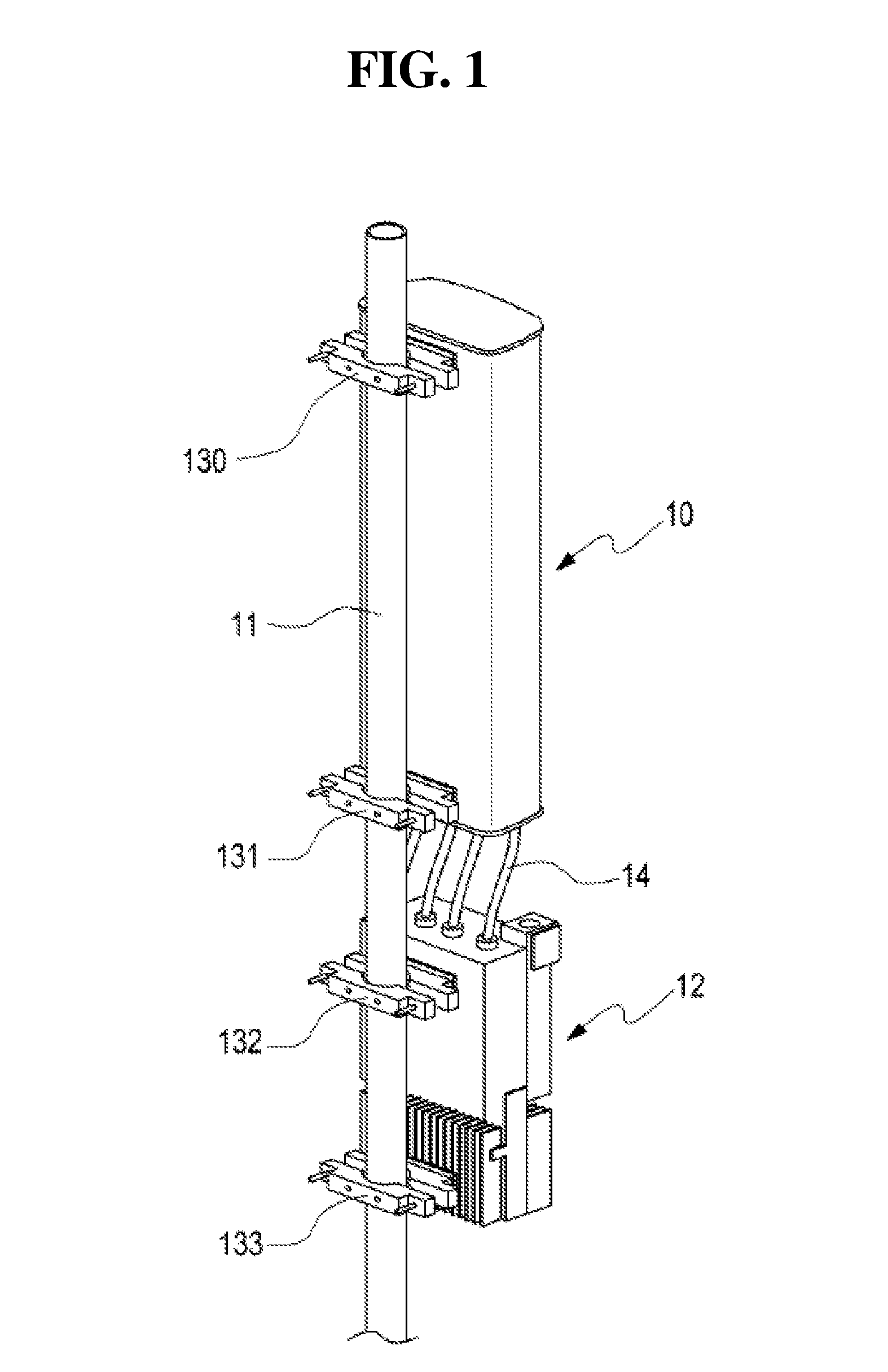
The arrangement of the antenna unit requires a plurality of fixing brackets and cables in order to mount the antenna module and the repeater to each other, and thus, corresponds to the reason for an increase in installation costs.
Further, in the conventional antenna unit, the antenna module and the repeater are mounted along a support, respectively, so that large costs are required for installation, maintenance, and a rental space of the antenna space, and a large mounting space is required when the antenna unit is installed, so that rental costs are increased.

Method used


Image

  • Antenna device of base station
  • Antenna device of base station
  • Antenna device of base station

Examples


Embodiment Construction

[0044]The following description with reference to the accompanying drawings is provided to help whole understanding of embodiments of the present disclosure as defined by the claims and the equivalents of the claims. Although the following description includes various specific details in order to help the understanding, the details will be considered to be exemplary matters Therefore, it will be understood by a person skilled in the art that variations and modifications of the embodiments described in the disclosure can be achieved without departing from the scope and spirit of the present invention. Further, the description of well-known functions and structures will be omitted for definition and simplicity. The term “substantially” may imply that it is unnecessary that cited features, parameters or values are not accurately achieved, and an allowance error, a measurement error, a measurement accuracy limit, and a deviation, a change or a feature including other components known to...


PUM


Abstract

Various embodiments of the present invention comprise: an antenna module; and at least one RRH which is arranged to face the outer surface of the antenna module, is coupled by being directly connected to the antenna module and arranged along the longitudinal direction of the antenna module, wherein a plurality of cooling air gaps are provided between the outer surface of the antenna module and the RRH.

Description

CROSS REFERENCE TO RELATED APPLICATIONS[0001]This application is a continuation of International Application No. PCT / KR2014 / 010815 filed on Nov. 11, 2014, which claims priorities to Korean Application No. 10-2013-0140014 filed on Nov. 18, 2013, which applications are incorporated herein by reference.TECHNICAL FIELD[0002]Various embodiments of the present disclosure relate to an antenna unit for a base station, and relate to, for example, a Radio Remote Head (RRH) for receiving a signal from an antenna and a base station.BACKGROUND ART[0003]In a mobile communication system, the term “base station” refers to a system for relaying radio waves of a portable terminal within a cell. The base station is mainly installed on the roof of a building to relay the radio waves of the portable terminal. Accordingly, base stations exist in units of cells and control incoming / outgoing signal transmission, traffic channel definition, and traffic channel monitoring in addition to interface functions b...

Claims


Application Information

Patent Timeline
Patent Type & Authority Applications(United States)
IPC IPC(8): H01Q1/24H01Q1/02H01Q1/12
CPCH01Q1/246H01Q1/02H01Q1/1207H01Q1/1228H01Q1/1264
Inventor KIM, DUK-YONGMOON, YOUNG-CHANYOO, CHANG-WOOPARK, MIN-SIKKIM, JEONG-MINYANG, HYOUNG-SEOKKIM, IN-HO
Owner KMW INC
Why Eureka
Try Eureka