
Method of making an LED lamp

a technology of led lamps and diodes, applied in the field of illumination, can solve the problems of low use value of led lighting for such uses, low use value, and high maintenance cost, and achieve the effects of reducing hazards, minimizing installation costs, and improving component service li

Inactive Publication Date: 2015-04-16
LED WAVES
View PDF1 Cites 15 Cited by
  • Summary
  • Abstract
  • Description
  • Claims
  • Application Information

AI Technical Summary

Benefits of technology

The solid state LED luminaire is a new type of LED lamp that solves the problem of heat dissipation, which is a big issue with traditional lamps like incandescent and LED lamps. It uses a large plate to create better heat removal, resulting in higher performance and longer lasting compared to other LED lamps. The LED luminaire is also safer, as it reduces hazards and can be used in a variety of environments. Additionally, it can be easily installed in existing incandescent fixtures, reducing installation costs and improving service life. The LED luminaire is also resistant to shock and vibration, making it suitable for both rugged and everyday installations.

Problems solved by technology

No protective case is used in standard applications involving residential / commercial / industrial CFL units.
Previously, LED lighting for such uses has been minimal or even disfavored because LED lights in such applications were low intensity dictated by the inherent difficulties in removing heat in a water tight enclosure needed for such uses.
While heretofore considered necessary, such lighting is a high-operating and high-maintenance option due to the high current required and the frequent need for replacing burned-out bulbs.

Method used


Image

  • Method of making an LED lamp
  • Method of making an LED lamp
  • Method of making an LED lamp

Examples


Embodiment Construction

[0046]In the following description, reference is made to the accompanying drawings, which form a part hereof and which illustrate several embodiments of the present invention. The drawings and the preferred embodiments of the invention are presented with the understanding that the present invention is susceptible of embodiments in many different forms and, therefore, other embodiments may be utilized and structural, and operational changes may be made, without departing from the scope of the present invention. For example, the steps in the method of the invention may be performed in any order that results making or using the luminaire described herein.

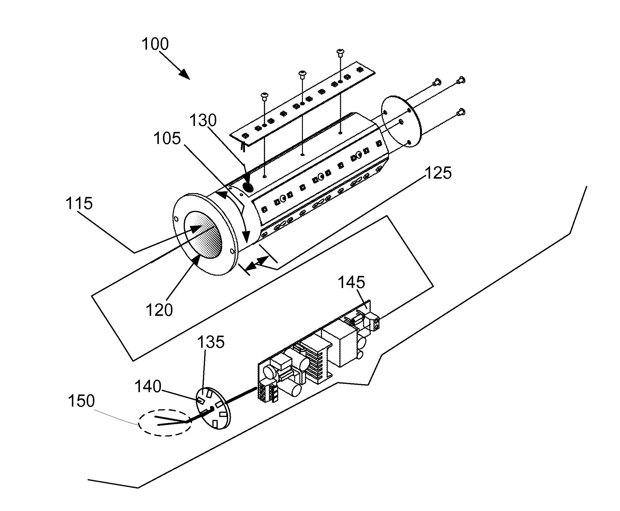
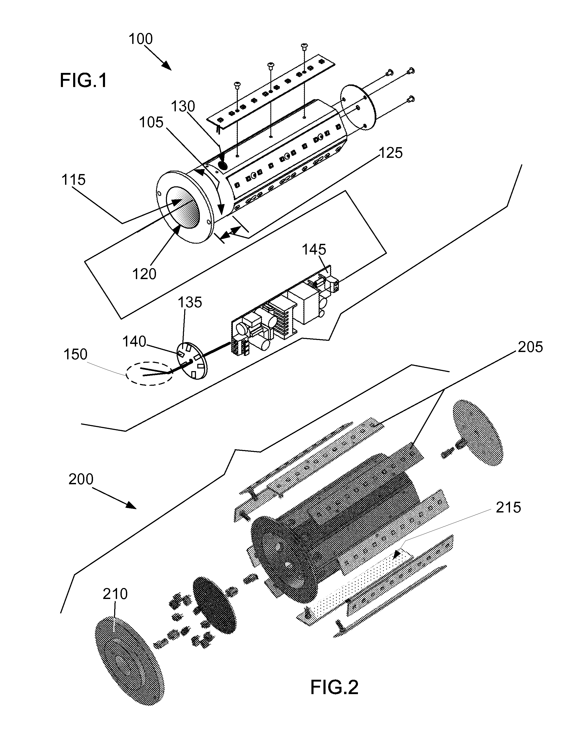
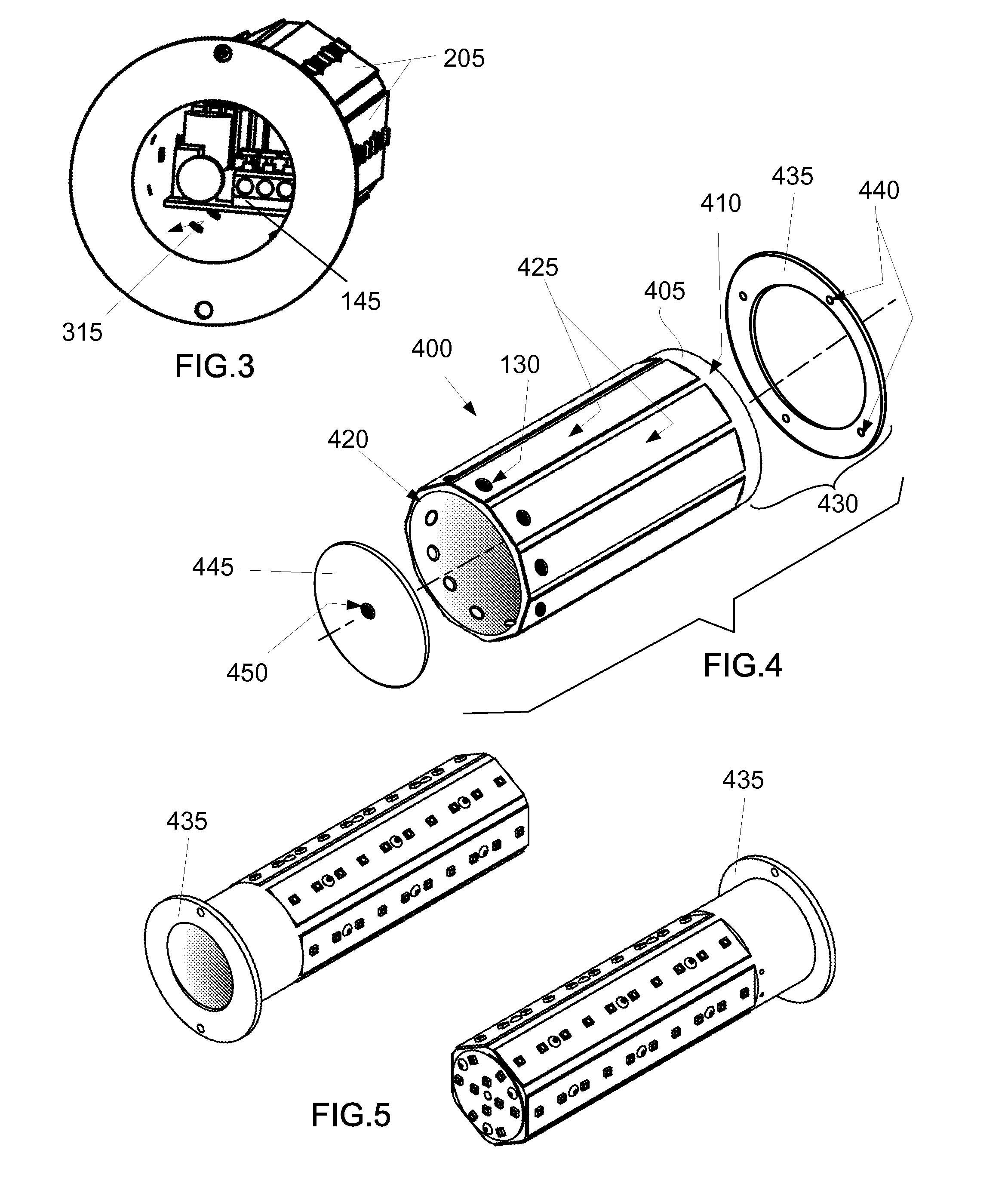
[0047]FIG. 1 is an exploded perspective view of an exemplary light emitting diode (LED) lamp (100), also referred to herein as a luminaire. The light emitting diode (LED) lamp (100) has a heat sink (400), a driver circuit board (145), flat LED boards (205), a circular LED board (620), and a turret connector board (135).

[0048]The heat s...


PUM

PropertyMeasurementUnit
temperatureaaaaaaaaaa
heat conductingaaaaaaaaaa
distanceaaaaaaaaaa

Abstract

A method of making a light emitting diode (LED) lamp is disclosed. Included are steps of: providing a metal heat sink having a cylindrical portion formed with flat planar surfaces extending longitudinally around the outer surface; providing flat LED boards that are attached to the flat planar surfaces; providing a circular LED board mounted to the top end of the cylindrical portion; providing a turret connector board with electrical connection ports to electrically join the LED boards; providing a driver circuit board and electrically connecting it to the turret connector board; connecting the flat LED boards to the driver circuit board; securing the circular LED board to the top open-end; and securing the flat LED boards to the flat planar surfaces. Optional steps include: providing a mounting plate of heat conducting metal; applying thermal compound; providing and installing a transparent cover; providing and attaching a mount to the incandescent lamp.

Description

TECHNICAL FIELD[0001]In the field of illumination, a method of making a high-intensity light emitting diode (LED) luminaire that greatly improves heat dissipation using a solid base of metal and in a configuration that enables significant additional light emission from LED chips.BACKGROUND ART[0002]The present invention has application where high intensity, long-life lighting is needed. Typical uses may include an indoor or outdoor application, a wet location, a hazardous location, and a waterproof location. The invention has application to commercial, residential, retail and industrial applications in general, in both wet locations and dry locations.[0003]LED chips enable greater lamp life. The present invention is suitable for retrofit and replacement applications using differing mounts. Such application enables LED use where traditional lighting was previously employed, either indoors, where the LED lamp may be used for replacement of a standard light bulb, such as an A-19 type l...

Claims


Application Information

Patent Timeline
Patent Type & Authority Applications(United States)
IPC IPC(8): F21K99/00F21V29/00
CPCF21K9/90F21V29/22F21K9/30F21V23/006F21K9/232F21Y2115/10F21Y2107/30F21K9/238Y10T29/49126
Inventor ROWLEY, LARRY W.SLAVIS, JOEL
Owner LED WAVES
Learn More