Integrated electronic RF shielding apparatus for an MRI magnet

a shielding apparatus and electronic technology, applied in the field of magnetic resonance imager system and components, can solve the problems of image artifacts, inducing rf noise, and limited availability in examining facilities, such as hospitals, and achieve the effects of reducing the cost of examining facilities, and reducing the cost of examining

Inactive Publication Date: 2006-05-30
GE MEDICAL SYST GLOBAL TECH CO LLC
View PDF17 Cites 4 Cited by
  • Summary
  • Abstract
  • Description
  • Claims
  • Application Information

AI Technical Summary

Benefits of technology

[0008]The present invention provides an integrated electronic system housing and magnet structure for an imaging system. The integrated structure includes a housing and a radio frequency shield. The housing is coupled to the magnet structure and contains imaging system support electronics. The radio frequency shield is coupled to the housing and prevents radio frequency interference of a radio frequency (RF) receiver coil from the imaging system support electronics.
[0009]The embodiments of the present invention provide several advantages. One such advantage is the provision of an integrated structure that isolates the RF noise, generated from imaging system support electronics, from the imaging system RF receiver antenna. In so doing, the stated embodiments prevent generation of image artifacts and allow the close proximity and installation of the imaging system electronics and the magnet structure within a single room. Thus, the stated embodiment minimizes space usage of an imaging system and costs involved therein. The installation within a single room of the imaging system support electronics and the magnet structure also minimizes installation costs of the imaging system.
[0010]Another advantage that is provided by multiple embodiments of the present invention is the provision of a radio frequency shield that prevents radio frequency interference between a magnetic field, of the magnetic structure, and the imaging system support electronics. By minimizing radio frequency interference, electrical connection troubleshooting is minimized, and thus, maintenance costs involved therein is also minimized.

Problems solved by technology

When a break or varying contact between electrical connections occurs in the magnetic field of the magnet RF noise is induced in the magnetic field that causes image artifacts.
Image artifacts can even be caused by the motion or rubbing of braided wire, which also induces RF noise.
Thus, any metal-to-metal contact on or near the magnet structure can have varying contact and be a source of image artifacts.
Floor space within an examining facility, such as a hospital, is costly and has limited availability.
Also, in order to have the electronics separate from the magnet structure, additional tasks are performed by the MRI system manufacturer, which increases costs of the MRI system.

Method used


Image

  • Integrated electronic RF shielding apparatus for an MRI magnet
  • Integrated electronic RF shielding apparatus for an MRI magnet
  • Integrated electronic RF shielding apparatus for an MRI magnet

Examples


Embodiment Construction

[0016]While the present invention is described with respect to an apparatus for radio frequency shielding an magnetic resonance imaging (MRI) magnet structure from MRI system supporting electronics for proximate and integrated coupling therebetween, the following apparatus is capable of being adapted for various purposes and is not limited to the following applications: MRI systems, computed tomography systems, x-ray imaging systems, radiotherapy systems, and other applications requiring the isolation of system electronics from magnetic or magnetic field generating structures known in the art.

[0017]In the following description, various operating parameters and components are described for one constructed embodiment. These specific parameters and components are included as examples and are not meant to be limiting.

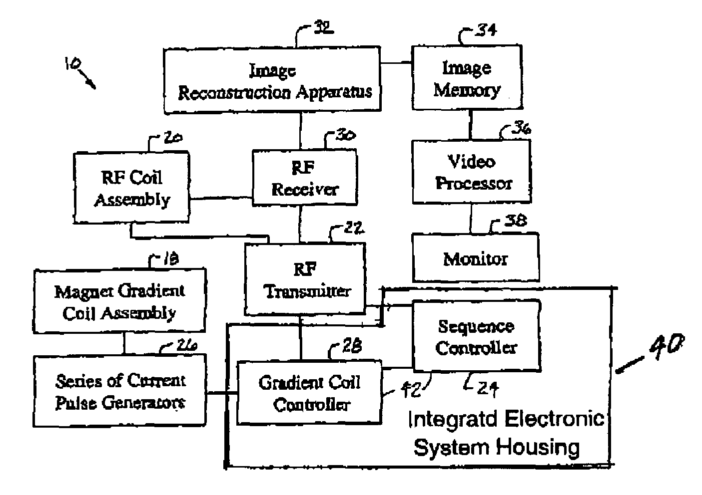
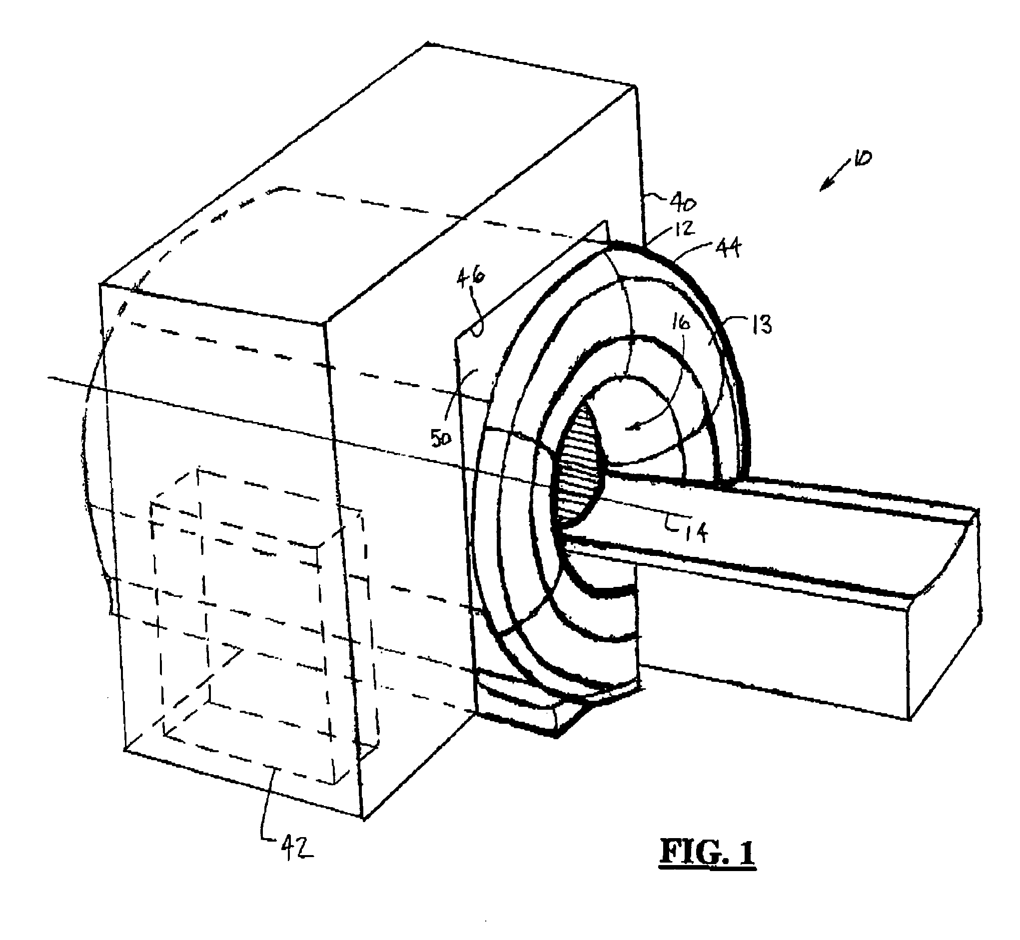
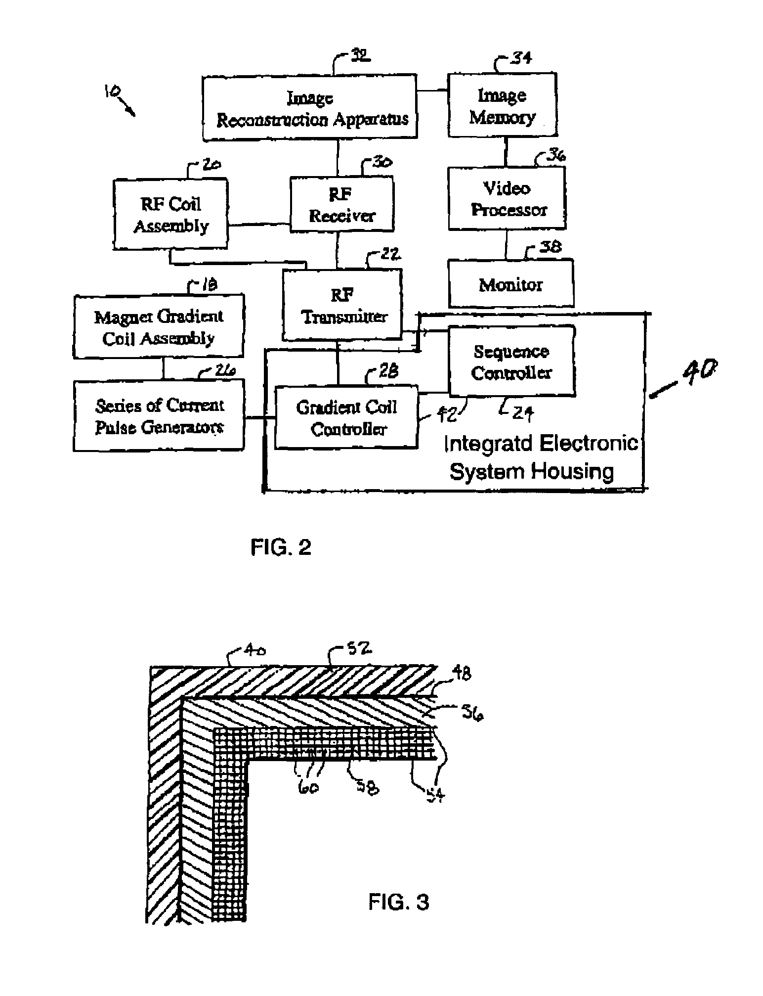
[0018]Referring now to FIGS. 1 and 2, a perspective view of a MRI system 10 incorporating an integrated electronic system housing and magnet structure 12 and a block diagra...


PUM


Abstract

An integrated electronic system housing and magnet structure (12) for an imaging system (10) includes a housing (40) and a radio frequency shield (46). The housing (40) is coupled to the magnet structure (13) and contains imaging system support electronics (42). The radio frequency shield (46) is coupled to the housing (40) and prevents radio frequency interference of a radio frequency receiver coil (30) from the imaging system support electronics (42).

Description

BACKGROUND OF INVENTION[0001]The present invention relates generally to magnetic resonance imager (MRI) systems and components. More particularly, the present invention relates to radio frequency shielding of an MRI magnet structure from MRI system supporting electronics for proximate and integrated coupling therebetween.[0002]Current Magnetic Resonance Imager (MRI) systems include a superconducting magnet structure that generates a temporally constant primary magnetic field. The superconducting magnet is used in conjunction with a magnetic gradient coil assembly, which is sequentially pulsed to create a sequence of controlled gradients in the static magnetic field during a MRI data gathering sequence. The controlled sequential gradients are effectuated throughout a patient imaging volume (patient bore), which is coupled to one or more MRI radio frequency (RF) coils or antennae. The RF coils are located between the magnetic gradient coil assembly and the patient bore.[0003]As a part...

Claims


Application Information

Patent Timeline
Patent Type & Authority Patents(United States)
IPC IPC(8): G01V3/00A61B5/055G01R33/422
CPCG01R33/422G01R33/28G01R33/42
Inventor HAVENS, TIMOTHY JOHN
Owner GE MEDICAL SYST GLOBAL TECH CO LLC
Why Eureka
Try Eureka