
Adjustment device for an automotive wing mirror

a technology for adjusting devices and wing mirrors, which is applied in the direction of gearing details, gearing, transportation and packaging, etc., can solve the problems of obstructing the driver's vision severely, weak vibration absorption in the peripheral zone of the adapter, and difficult to obtain compact and slim automotive wing mirror assemblies, etc., to achieve precise and reliable adjustment of the angle of the wing mirrors

Active Publication Date: 2016-09-15
HAOYONG AUTOMOTIVE CONTROLS LTD
View PDF2 Cites 7 Cited by
  • Summary
  • Abstract
  • Description
  • Claims
  • Application Information

AI Technical Summary

Benefits of technology

The adjustment device for an automotive wing mirror aims to provide a precise and reliable angle adjustment while keeping the wing mirror compact and lightweight. Additionally, the device should effectively absorb vibration to minimize the vibration transmitted to the wing mirror. The pivot connection structure firmly supports the shell and the adapter, while the elastic tabs in a circle effectively absorb vibration. The overall effect of the invention is a stable and secure adjustment of the automotive wing mirror.

Problems solved by technology

However, the pivot structure of the above-mentioned technique includes several complex components to become complicated, and it is difficult to obtain a compact and slim automotive wing mirror assembly because of the complicated pivot structure.
Furthermore, in the prior art, because traveling vibration transmitted from the outer side to the adapter is collected in and absorbed by the central region of the adapter, vibration absorption is weak in the peripheral zone of the adapter.
Thus, the peripheral region of the adapter relatively shakes more, and the shake of the adapter will be transmitted to the wing mirror, which will obstruct the driver's field of vision severely.

Method used


Image

  • Adjustment device for an automotive wing mirror
  • Adjustment device for an automotive wing mirror
  • Adjustment device for an automotive wing mirror

Examples


Embodiment Construction

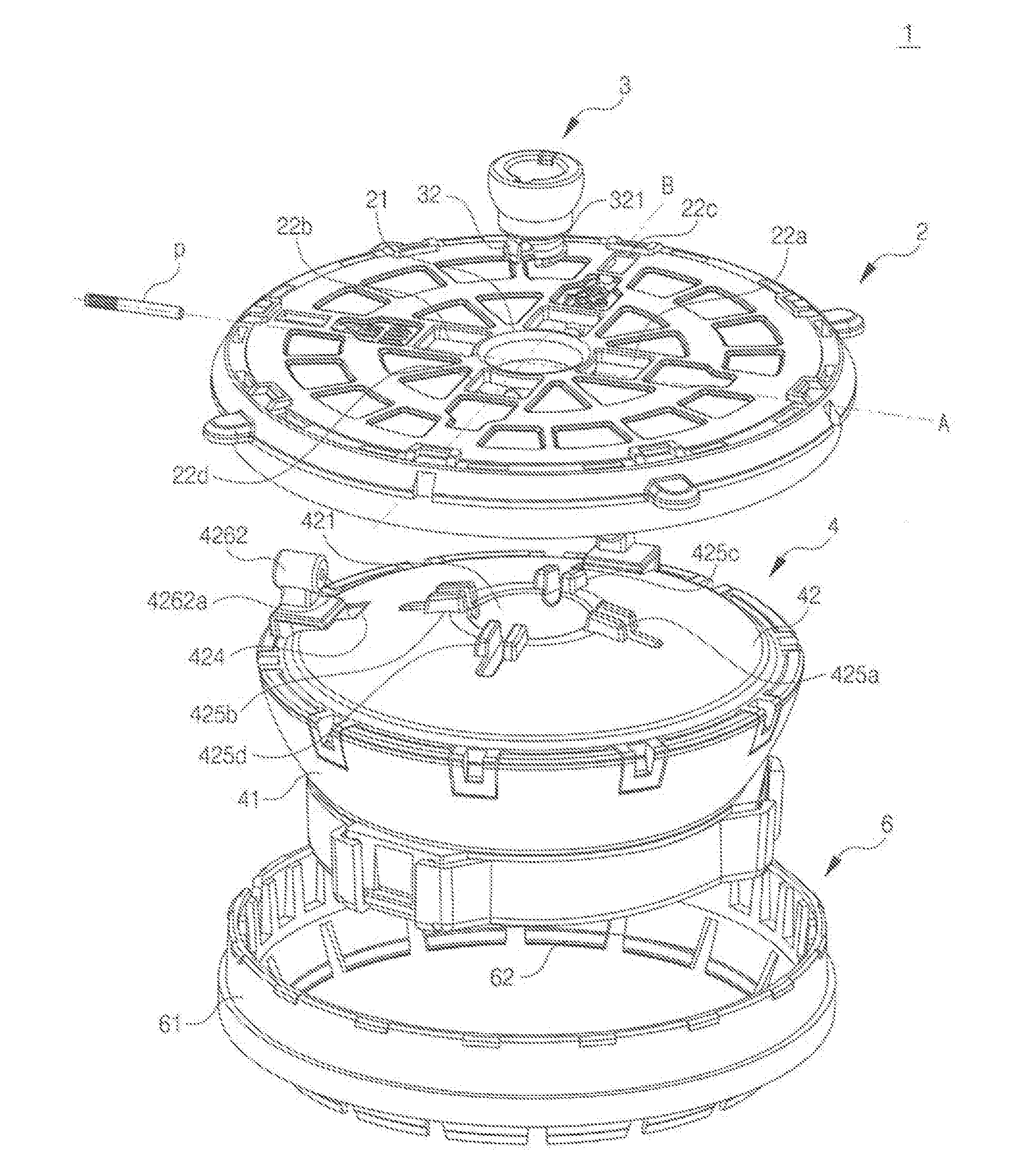
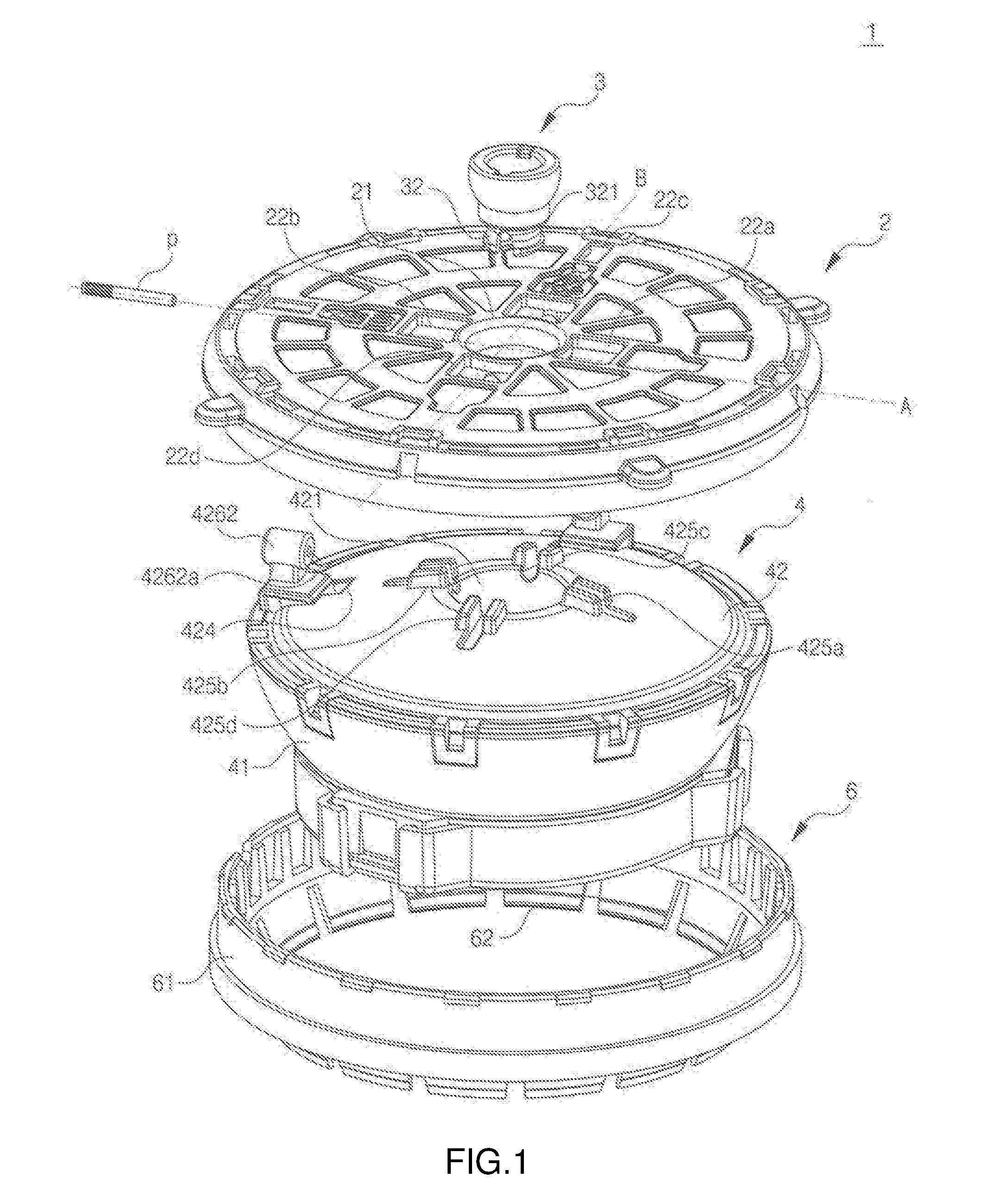
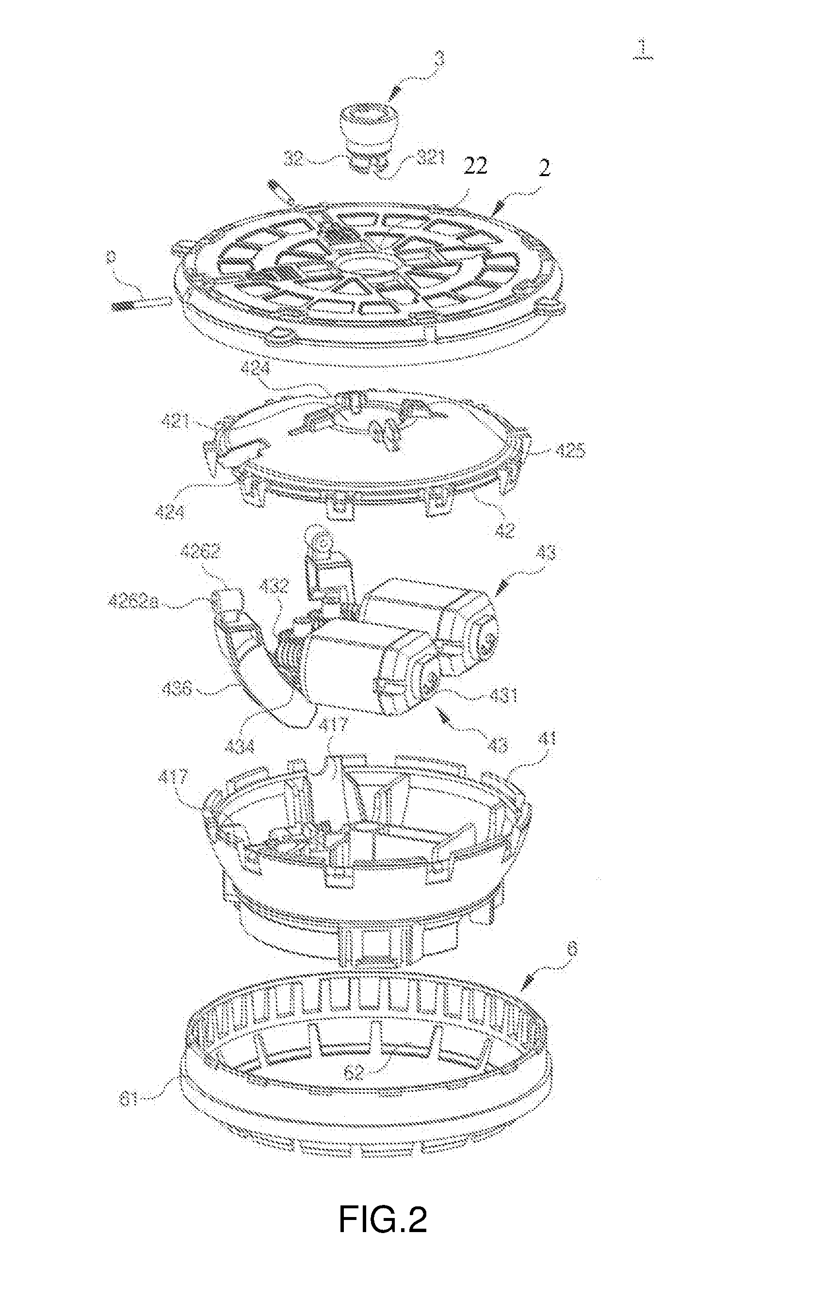
[0031]It should be noted that, without conflict, examples of the present application and the features of the examples can be combined with each other, the present invention will be described in further detail accompanying with the drawings and the following embodiments.

[0032]The following examples are described as skilled in the art to be able to fully convey the concept of the present invention. Thus, the present invention is not limited to the embodiments described below, and can be specific in other forms. Furthermore, for convenience, the drawings can be exaggerated to show constituent width, length, thickness, etc.

[0033]Referring to FIGS. 1 to 5, an embodiment of an adjustment device 1 for an automotive wing mirror is located inside a housing (not shown) of a wing mirror assembly, to adjust a position of the wing mirror. The adjustment device 1 includes an adapter 2 tightly fixed to the wing mirror, an adapter driving module 4 for driving the adapter 2 to adjust the wing mirror...


PUM


Abstract

An adjustment device for an automotive wing mirror includes an adapter fixed to the wing mirror and having a virtual rotation center and first and second virtual axes perpendicularly intersecting with each other relative to the virtual rotation center, and an adapter driving module to drive the adapter. The adapter driving module includes a bowl-shaped lower shell, an upper shell covering on the lower shell, and two actuator mechanisms. Each actuator mechanism includes a driving motor, a reduction gear set, a clutch assembly meshing with the reduction gear set, and a ring gear meshing with the clutch assembly. The ring gears partially extend through the upper shell and are connected to the adapter on the first virtual axis and the second virtual axis. The adapter is operable of revolving relative to the virtual rotation center in two intersecting directions.

Description

BACKGROUND OF THE INVENTION[0001]The present invention relates to automobiles, and more particularly to an adjustment device for a wing mirror of an automobile.[0002]Currently, to enable a driver to easily observe traffic situation around a rear side of an automobile, wing mirrors are mounted to both sides of the automobile and in front of front doors of the automobile. A wing mirror assembly includes a housing, a wing mirror located at a side of the housing and angularly adjustable, and an adjustment device mounted in the housing to adjust an angle of the wing mirror. The adjustment device generally includes a power-actuator unit driven by a power source to adjust the angle of the wing mirror, and a manual-actuator unit to manually adjust the angle of the wing mirror.[0003]A Korean patent with register No. 10-0539070, which is named “Mechanism for Adjusting an Automotive Wing Mirror Assembly”, applied in Dec. 16, 2003, and registered in Dec. 20, 2005, is disclosed. The mechanism in...

Claims


Application Information

Patent Timeline
Patent Type & Authority Applications(United States)
IPC IPC(8): B60R1/072
CPCB60R1/072B60R1/06B60R1/064B60R1/066B60Y2200/11F16H1/16F16H1/225F16H1/28F16H57/0006F16H57/028
Inventor CHONG, KYONGCHOL
Owner HAOYONG AUTOMOTIVE CONTROLS LTD
Learn More