Underwater vehicle for transporting fluids such as for example natural gas, oil or water, and process for using said vehicle

a technology for transporting fluids and vehicles, which is applied in the direction of special purpose vessels, vessel construction, and borehole/well accessories, etc., can solve the problems of increasing transportation costs, increasing transportation costs, and hydrates having a much greater specific weigh

Inactive Publication Date: 2016-09-22
ENI SPA
View PDF2 Cites 5 Cited by
  • Summary
  • Abstract
  • Description
  • Claims
  • Application Information

AI Technical Summary

Benefits of technology

This patent describes an underwater vehicle and a procedure for its use. The vehicle has a unique design that allows for better maneuverability and stability in water. It can be equipped with a removable module for different tasks and can also emergency conditions. The procedures described in the patent allow for the safe and effective use of the vehicle. The technical effects of this invention are improved maneuverability and stability in water, as well as better operability and reliability of the underwater vehicle for various tasks.

Problems solved by technology

According to the authors of the present invention, this type of tank does not have a particular structural robustness; furthermore the considerable variability of the form and volume of the flexible bag in relation to the filling degree increases the fluid-dynamic resistance to advancement and makes it more difficult to balance the load and distribute it as desired.
The transformation of natural gas to hydrates and the reverse transformation when the tank is discharged, increase the transportation costs; furthermore, hydrates have a much greater specific weight with respect to compressed or liquefied natural gas, and in any case greater than oil, and this makes the floating of the tank more difficult; finally, it seems that no-one has so far succeeded in developing an economically convenient procedure for storing and transporting gas through hydrates.
The mechanical structure of this third variant is, according to the authors of the present invention, relatively complex and costly to construct, and also relatively heavy and not mechanically robust.
The authors of the present invention, however, believe that the known underwater tanks previously described do not allow a sufficiently economical or safe transportation.

Method used


Image

  • Underwater vehicle for transporting fluids such as for example natural gas, oil or water, and process for using said vehicle
  • Underwater vehicle for transporting fluids such as for example natural gas, oil or water, and process for using said vehicle
  • Underwater vehicle for transporting fluids such as for example natural gas, oil or water, and process for using said vehicle

Examples


Embodiment Construction

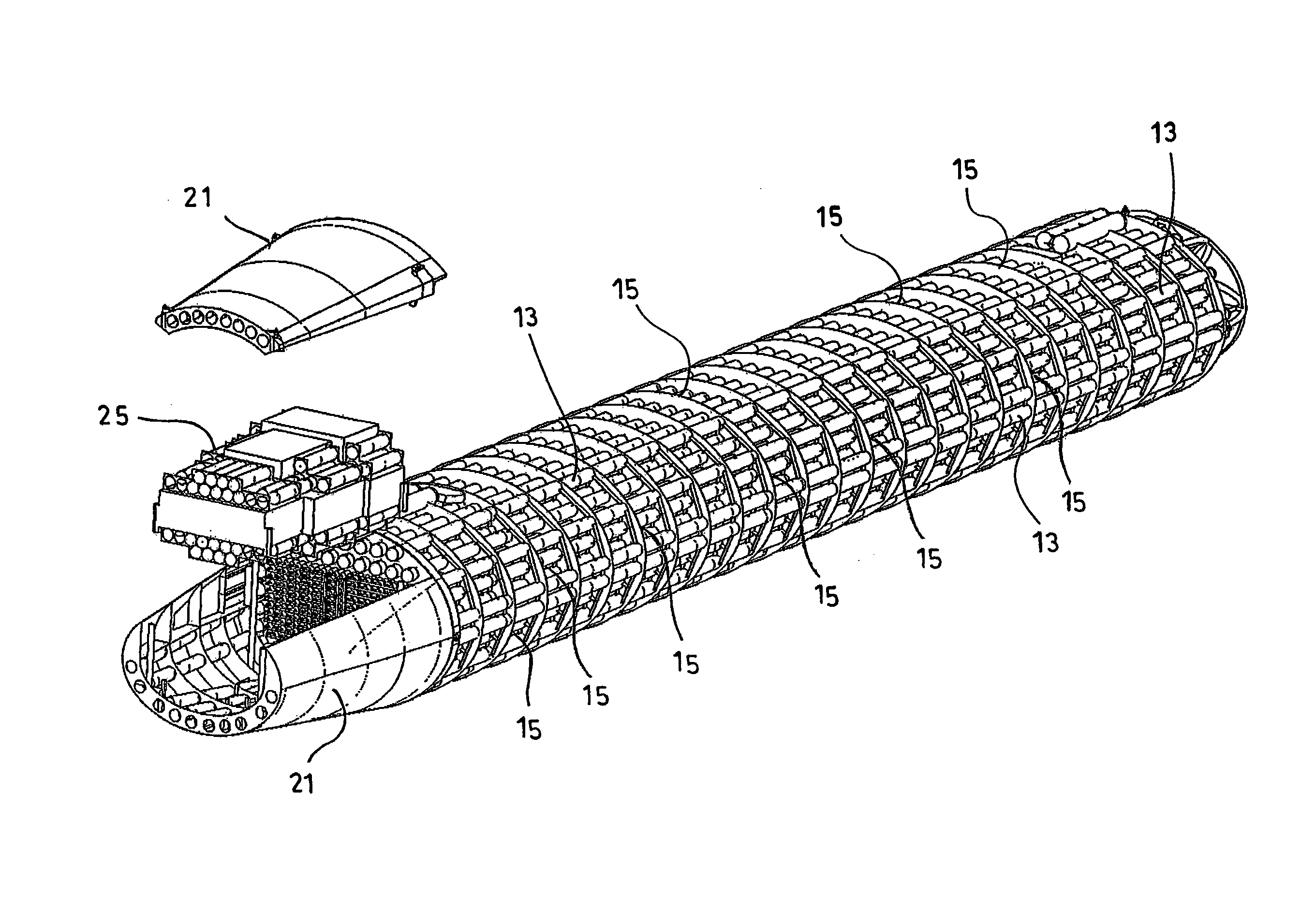
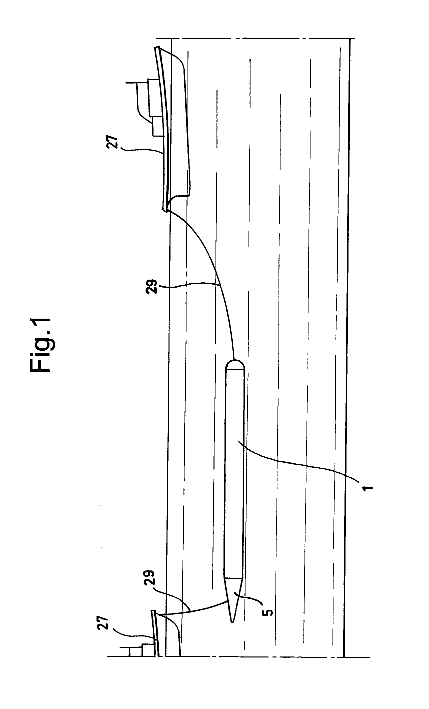
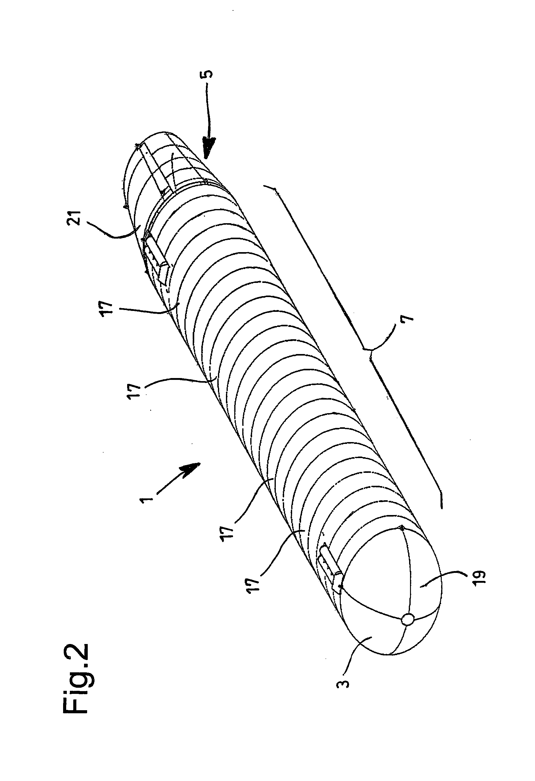
[0020]FIGS. 1 to 7 relate to an underwater vehicle for transporting fluids such as, for example, natural gas, oil or water, and a transporting system which adopts this, according to a particular embodiment of the present invention. The underwater vehicle, indicated with the overall reference number 1, is particularly suitable for exploiting wells from which prevalently gas is extracted, and together with this, a possible marginal fraction of oil and / or water. The vehicle 1 as a whole has an elongated form, advantageously like a torpedo.

[0021]The underwater vehicle 1 preferably has a streamlined tip 3, i.e. for example, a hemispherical, ogival, ovoid, conical or in any case tapered cap, and a drop-shaped or in any case tapered tail 5, so as to reduce fluid-dynamic resistances to underwater advancement; it can have sides 7 having transversal sections with a substantially constant form and dimensions; the sides 7 can therefore be substantially cylindrical or prismatic.

[0022]The transve...


PUM

PropertyMeasurementUnit
external pressureaaaaaaaaaa
internal pressureaaaaaaaaaa
operational depthaaaaaaaaaa

Abstract

An underwater vehicle for transporting extraction fluids, for example natural gas, oil or water, has an overall elongated form and includes one or more containment tubes configured to contain the fluid to be transported and forming a bundle that prevalently extends longitudinally with respect to the underwater vehicle, making the vehicle structurally more robust and intrinsically safe.

Description

FIELD OF THE INVENTION[0001]The present invention relates to an underwater vehicle for transporting fluids such as, for example, natural gas, oil or water, and a process for using said vehicle.STATE OF THE ART[0002]Tanks designated to remain completely submerged while they are being towed by a vessel for transporting natural gas or oil, as an alternative to fixed pipes lying on seabeds or ocean-beds or to tankers, are known. Examples of this transportation procedure are described in the documents US 2011 / 0000546, U.S. Pat. No. 3,975,167 and U.S. Pat. No. 6,260,501.[0003]The document US 2011 / 0000546 describes a first example of an underwater tank comprising a steel cage containing a flexible bag, destined for containing the gas or oil to be transported. According to the authors of the present invention, this type of tank does not have a particular structural robustness; furthermore the considerable variability of the form and volume of the flexible bag in relation to the filling degr...

Claims


Application Information

Patent Timeline
Patent Type & Authority Applications(United States)
IPC IPC(8): B63G8/00B63B13/00B63B21/50B63B21/56E21B41/04F25J3/08E21B43/40B01D53/22B01D46/24B01D53/047C10G7/00B63B25/12E21B43/01
CPCB63G8/001F25J2220/66B63B13/00B63B21/50B63B21/56E21B41/04E21B43/01E21B43/40B01D53/22B01D46/2403B01D53/047C10G7/00F25J3/08B63B2025/085B63B2207/02B63B2702/12B63B25/12E21B43/35
Inventor CARMINATI, STEFANONISTA, ALESSIO
Owner ENI SPA
Why Eureka
Try Eureka