
Rotating optical range finder

a technology of optical range finder and rotating shaft, which is applied in the direction of electromagnetic wave reradiation, measurement devices, instruments, etc., can solve the problems of troublesome incurring a larger error and the inconvenient measurement of the ruler, and achieve the effect of convenient rotation

Active Publication Date: 2016-09-22
ARIMA LASERS CORP
View PDF2 Cites 24 Cited by
  • Summary
  • Abstract
  • Description
  • Claims
  • Application Information

AI Technical Summary

Benefits of technology

The patent describes a rotating optical range finder that uses wireless power transfer to avoid the need for additional electricity components between its stationary and rotating bases. This makes the rotating base easier to move and increases the durability of the device. The finder is continuously rotating while measuring distances, and because there is no electricity transfer component, there is less weight and space usage. This also reduces the likelihood of damage during rotation.

Problems solved by technology

Due to the limitation in length, the ruler is not suitable to measure a long distance.
Further, it is troublesome to incur a larger error as conducting a longer distance measurement.

Method used


Image

  • Rotating optical range finder
  • Rotating optical range finder
  • Rotating optical range finder

Examples


Embodiment Construction

[0030]In the following detailed description, for purposes of explanation, numerous specific details are set forth in order to provide a thorough understanding of the disclosed embodiments. It will be apparent, however, that one or more embodiments may be practiced without these specific details.

[0031]In other instances, well-known structures and devices are schematically depicted in order to simplify the drawings.

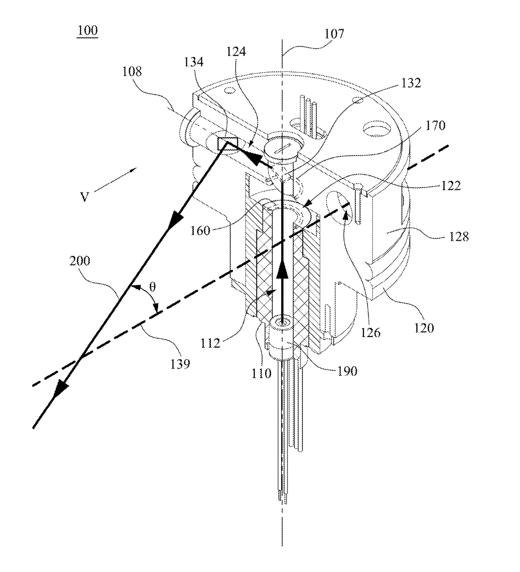
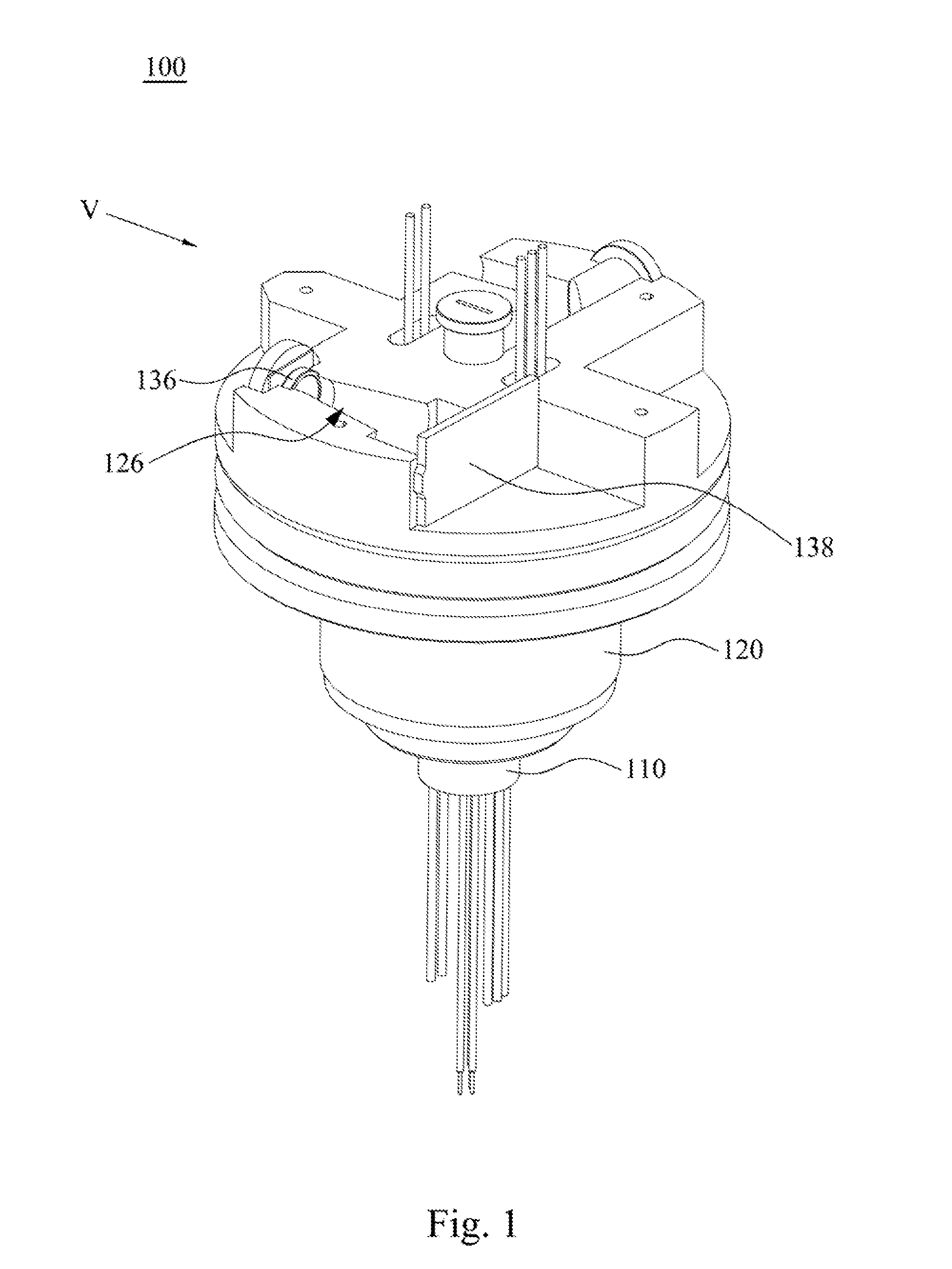
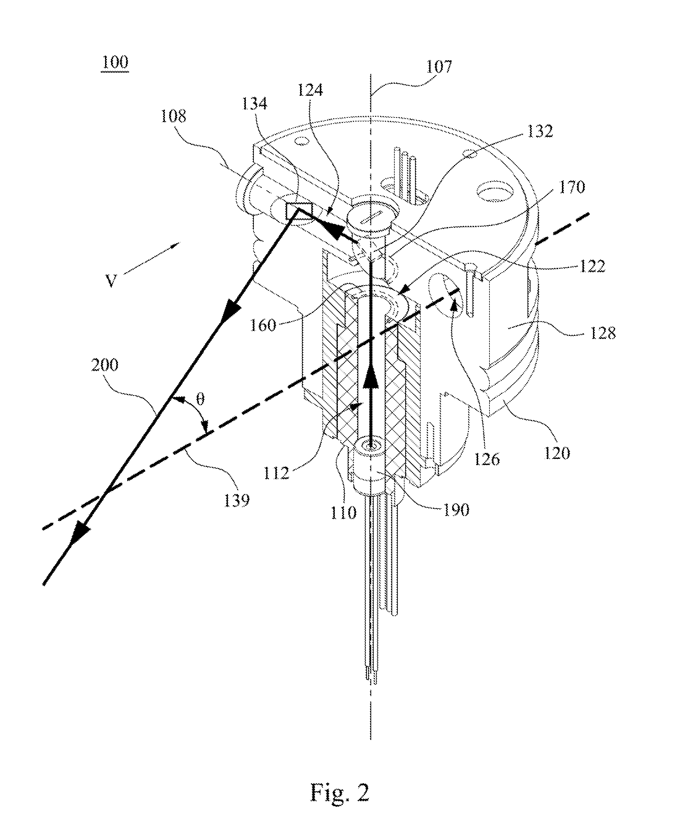
[0032]FIG. 1 is a schematic perspective view of a rotating optical range finder 100 according to one embodiment of this invention. A rotating optical range finder 100 is provided. The rotating optical range finder 100 measures distances between the rotating optical range finder 100 and surroundings. The rotating optical range finder 100 can rotate all-round, so the rotating optical range finder 100 can measure distances between the rotating optical range finder 100 and the surroundings. The rotating optical range finder 100 can be used in a robot module. By measuring the di...


PUM


Abstract

A rotating optical range finder includes a stationary base, a rotating base, an optical sensor, a transmitting circuit, a receiving circuit, a first induction coil, and a second induction coil. The rotating base s disposed on the stationary base. The optical sensor is disposed in the rotating base. The transmitting circuit is disposed in the stationary base. The receiving circuit is disposed in the rotating base and electrically connected to the optical sensor. The first induction coil is disposed in the stationary base and electrically connected to the transmitting circuit. The second induction coil is disposed in the rotating base and electrically connected to the receiving circuit.

Description

RELATED APPLICATIONS[0001]This application claims priority to Taiwan Application Serial Number 104204238, filed Mar. 20, 2015, the entirety of which is herein incorporated by reference.BACKGROUND[0002]1. Technical Field[0003]The present disclosure relates to an optical range finder, and more particularly, to a rotating optical range finder.[0004]2. Description of Related Art[0005]Distance measurement can be performed by direct measurement with a ruler or triangulation. Due to the limitation in length, the ruler is not suitable to measure a long distance. Triangulation is applicable to measure a long distance, but two persons are required in the measurement in that the observation mark is setup by a person, and the measuring instrument is controlled by another one. Further, it is troublesome to incur a larger error as conducting a longer distance measurement.[0006]Recently, laser range finders are more and more popular for the distance measurement, and thus becomes one of the most im...

Claims


Application Information

Patent Timeline
IPC IPC(8): G01S7/481H02J5/00G01S17/08
CPCG01S7/4817H02J5/005G01S17/08G01S7/003G01S17/42G01S17/48H02J50/12H02J50/90
Inventor WU, MING-CHOLIN, CHING-HUIFANG, MING-HUI
Owner ARIMA LASERS CORP
Learn More