Magnetic head for perpendicular magnetic recording including a coil having an inclined surface

a magnetic recording and perpendicular magnetic technology, applied in the field of magnetic recording head for perpendicular magnetic recording, can solve the problem of not being able to achieve further reduction of length of this magnetic head, and achieve the effect of suppressing variations in write characteristics, preventing the occurrence of unwanted erasure, and shortening the length of a magnetic path

Active Publication Date: 2016-09-22
HEADWAY TECH INC
View PDF5 Cites 3 Cited by
  • Summary
  • Abstract
  • Description
  • Claims
  • Application Information

AI Technical Summary

Benefits of technology

[0017]It is an object of the present invention to provide a magnetic head for perpendicular magnetic recording that is capable of preventing the occurrence of unwanted erasure induced by a skew, shortening the length of a magnetic path through the write shield, the return path section and the main pole, and suppressing variations in write characteristics, and to provide a method of manufacturing such a magnetic head.
[0033]In the magnetic head of the present invention, the top surface of the main pole includes the inclined portion. The specific coil element has the front end portion and the first inclined surface contiguous with the front end portion. The write shield includes the top shield layer. The top shield layer is located on the rear side in the direction of travel of the recording medium relative to an imaginary plane including the first inclined surface of the specific coil element. By virtue of such a configuration, the present invention makes it possible to prevent the occurrence of unwanted erasure induced by a skew, shorten the length of the magnetic path through the write shield, the return path section and the main pole, and suppress variations in write characteristics.

Problems solved by technology

Due to this configuration, it is not possible for this magnetic head to achieve further reduction in length of the aforementioned magnetic path by further reducing the distance between the medium facing surface and the end of the coil closest to the medium facing surface.

Method used


Image

  • Magnetic head for perpendicular magnetic recording including a coil having an inclined surface
  • Magnetic head for perpendicular magnetic recording including a coil having an inclined surface
  • Magnetic head for perpendicular magnetic recording including a coil having an inclined surface

Examples


first embodiment

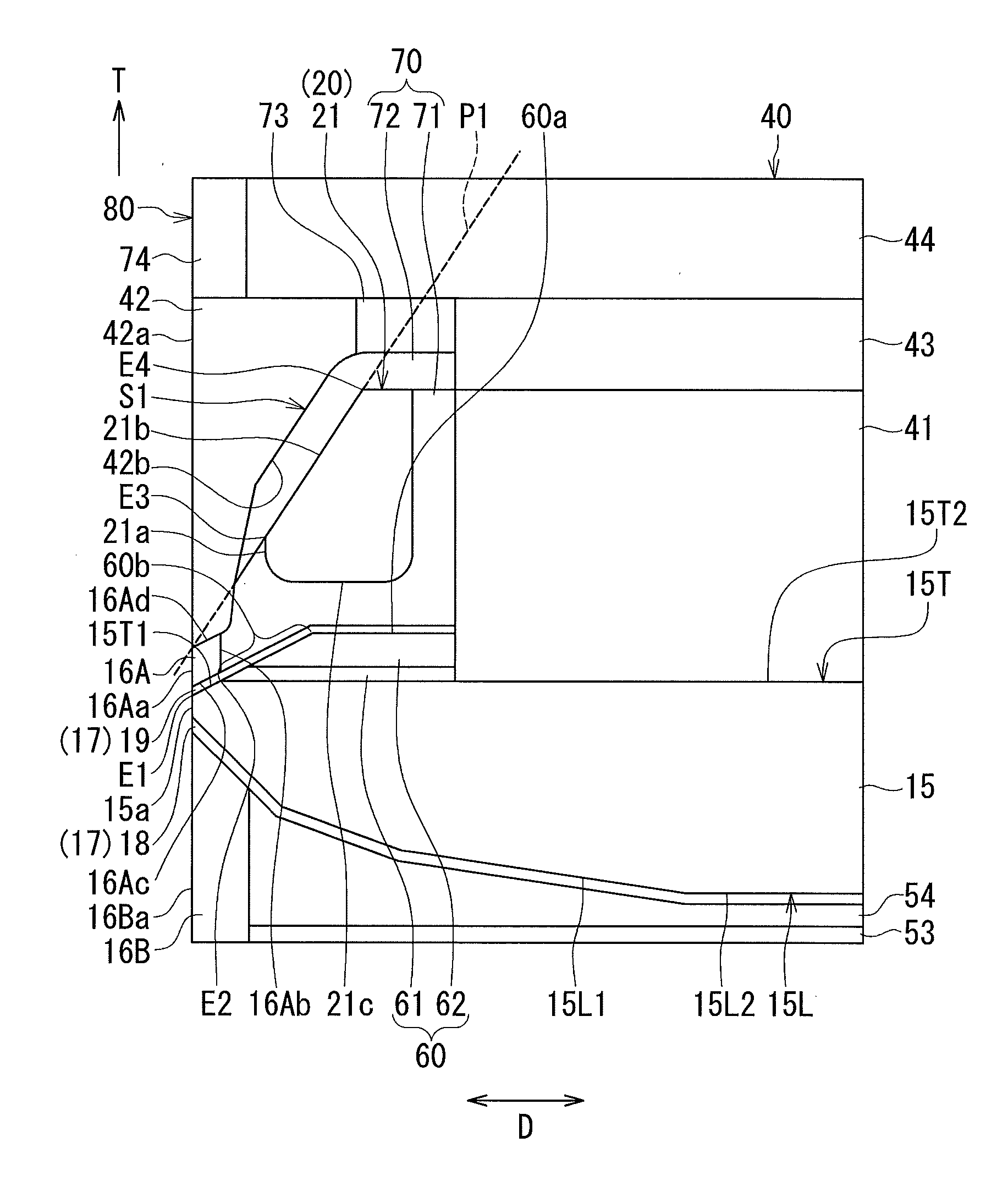
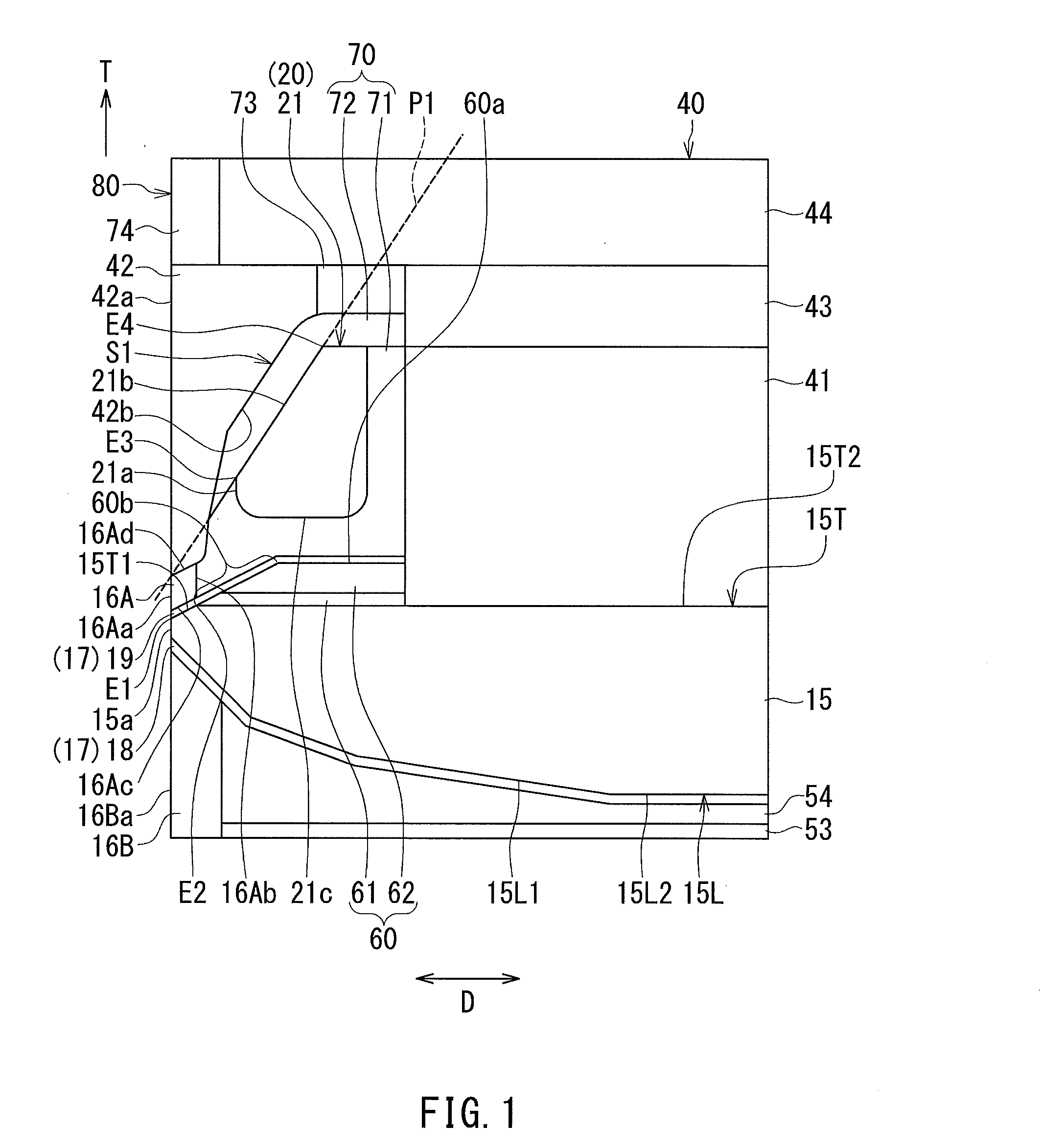
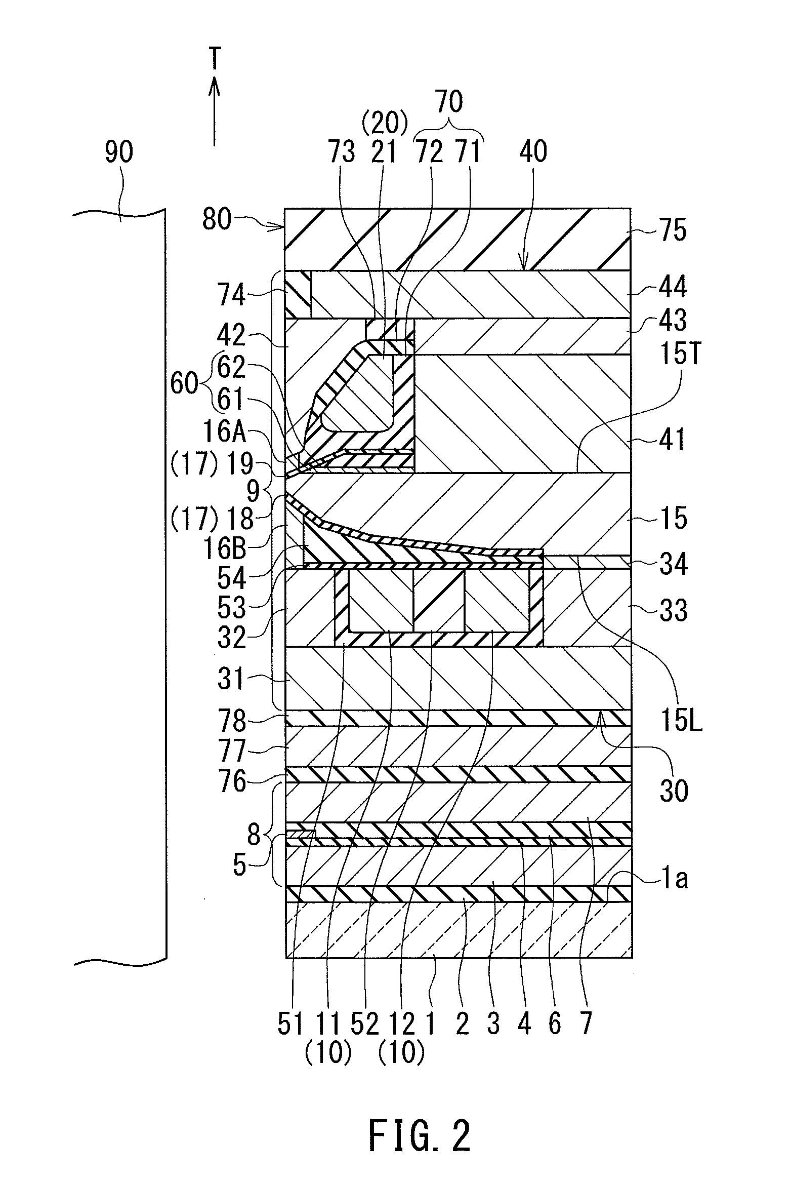
[0063]Preferred embodiments of the present invention will now be described in detail with reference to the drawings. First, reference is made to FIG. 2 to FIG. 5 to describe the configuration of a magnetic head for perpendicular magnetic recording (hereinafter simply referred to as magnetic head) according to a first embodiment of the invention. FIG. 2 is a cross-sectional view of the magnetic head according to the present embodiment. The arrow labeled T in FIG. 2 indicates the direction of travel of a recording medium. FIG. 3 is a front view showing the medium facing surface of the magnetic head according to the present embodiment. FIG. 4 is a plan view showing a second coil of the magnetic head according to the present embodiment. FIG. 5 is a plan view showing a first coil of the magnetic head according to the present embodiment. The arrow labeled TW in FIGS. 3 to 5 indicates the track width direction.

[0064]The magnetic head according to the present embodiment is for use in, for e...

second embodiment

[0150]A magnetic head according to a second embodiment of the present invention will now be described with reference to FIG. 14. FIG. 14 is a cross-sectional view showing the main part of the magnetic head according to the present embodiment. FIG. 14 shows a cross section perpendicular to the medium facing surface and to the top surface of the substrate, particularly the main cross section. The arrow labeled T in FIG. 14 indicates the direction of travel of the recording medium.

[0151]The magnetic head according to the present embodiment differs from the magnetic head according to the first embodiment in the following ways. The magnetic head according to the present embodiment includes a magnetic layer 45 in place of the magnetic layers 42, 43 and 44 of the first embodiment. The magnetic layer 45 is formed of a magnetic material and constitutes part of the first return path section 40. The nonmagnetic layer 73 is not provided in the present embodiment.

[0152]The magnetic layer 45 lies...

third embodiment

[0160]A magnetic head according to a third embodiment of the invention will now be described with reference to FIGS. 15 and 16. FIG. 15 is a cross-sectional view showing the main part of the magnetic head according to the present embodiment. FIG. 15 shows a cross section perpendicular to the medium facing surface and to the top surface of the substrate, particularly the main cross section. The arrow labeled T in FIG. 15 indicates the direction of travel of the recording medium. FIG. 16 is a plan view showing a first coil of the magnetic head according to the present embodiment. The arrow labeled TW in FIG. 16 indicates the track width direction.

[0161]The magnetic head according to the present embodiment differs from the magnetic head according to the first embodiment in the following ways. The magnetic head according to the present embodiment includes a first coil 120 in place of the first coil 20 of the first embodiment. As shown in FIG. 16, the first coil 120 is wound approximatel...


PUM

PropertyMeasurementUnit
thicknessaaaaaaaaaa
thicknessaaaaaaaaaa
heightaaaaaaaaaa

Abstract

A magnetic head includes a coil, a main pole, a write shield, a gap section, and a return path section. The main pole has a top surface including an inclined portion and a flat portion. The coil includes a specific coil element. The specific coil element has a front end portion, and an inclined surface contiguous with the front end portion. The write shield includes a top shield layer located on the front side in the direction of travel of a recording medium relative to the main pole, and located closer to a medium facing surface than the specific coil element. The top shield layer is located on the rear side in the direction of travel of the recording medium relative to an imaginary plane including the inclined surface of the specific coil element.

Description

BACKGROUND OF THE INVENTION[0001]1. Field of the Invention[0002]The present invention relates to a magnetic head for perpendicular magnetic recording for use to write data on a recording medium by means of a perpendicular magnetic recording system.[0003]2. Description of the Related Art[0004]The recording systems of magnetic read / write apparatuses include a longitudinal magnetic recording system in which the magnetization of signals is directed along the plane of a recording medium (the longitudinal direction), and a perpendicular magnetic recording system in which the magnetization of signals is directed perpendicular to the plane of a recording medium. It is known that the perpendicular magnetic recording system is harder to be affected by thermal fluctuation of the recording medium and capable of providing higher linear recording density, compared with the longitudinal magnetic recording system.[0005]Magnetic heads for perpendicular magnetic recording typically have, like those f...

Claims


Application Information

Patent Timeline
Patent Type & Authority Applications(United States)
IPC IPC(8): G11B5/31G11B5/127
CPCG11B5/3116G11B5/3163G11B5/1278G11B5/10G11B5/17
Inventor SASAKI, YOSHITAKAITO, HIROYUKISATO, KAZUKIIKEGAWA, YUKINORIARAKI, HIRONORITANEMURA, SHIGEKI
Owner HEADWAY TECH INC
Why Eureka
Try Eureka