
Electronic apparatus case

Inactive Publication Date: 2016-09-29
SHARP KK
View PDF1 Cites 5 Cited by
  • Summary
  • Abstract
  • Description
  • Claims
  • Application Information

AI Technical Summary

Benefits of technology

The invention aims to solve the problem of difficulty and speed in accessing the display of an electronic device by providing an electronic apparatus case that allows for easy and quick opening and closing of the cover.

Problems solved by technology

According to the study of the present inventors, in the multi-function housing case for a conventional smart phone, there is a problem that a space for opening and closing of a cover covering a display of the smart phone is large (Problem 1).
Since the multi-function housing case for the conventional smart phone has Problem 1, for example, the case is not suitable for use in a crowded vehicle or in a crowd.
In addition, according to the study of the present inventors, in the notebook type e-book terminal case having a solar cell element, there is a problem that it is difficult to charge the e-book terminal while using the e-book terminal (Problem 2).
In such a case, since sunlight or illumination light is unlikely to be incident on the solar cell element provided in the front cover portion, it is difficult to charge the e-book terminal.

Method used


Image

  • Electronic apparatus case
  • Electronic apparatus case
  • Electronic apparatus case

Examples


embodiment 1

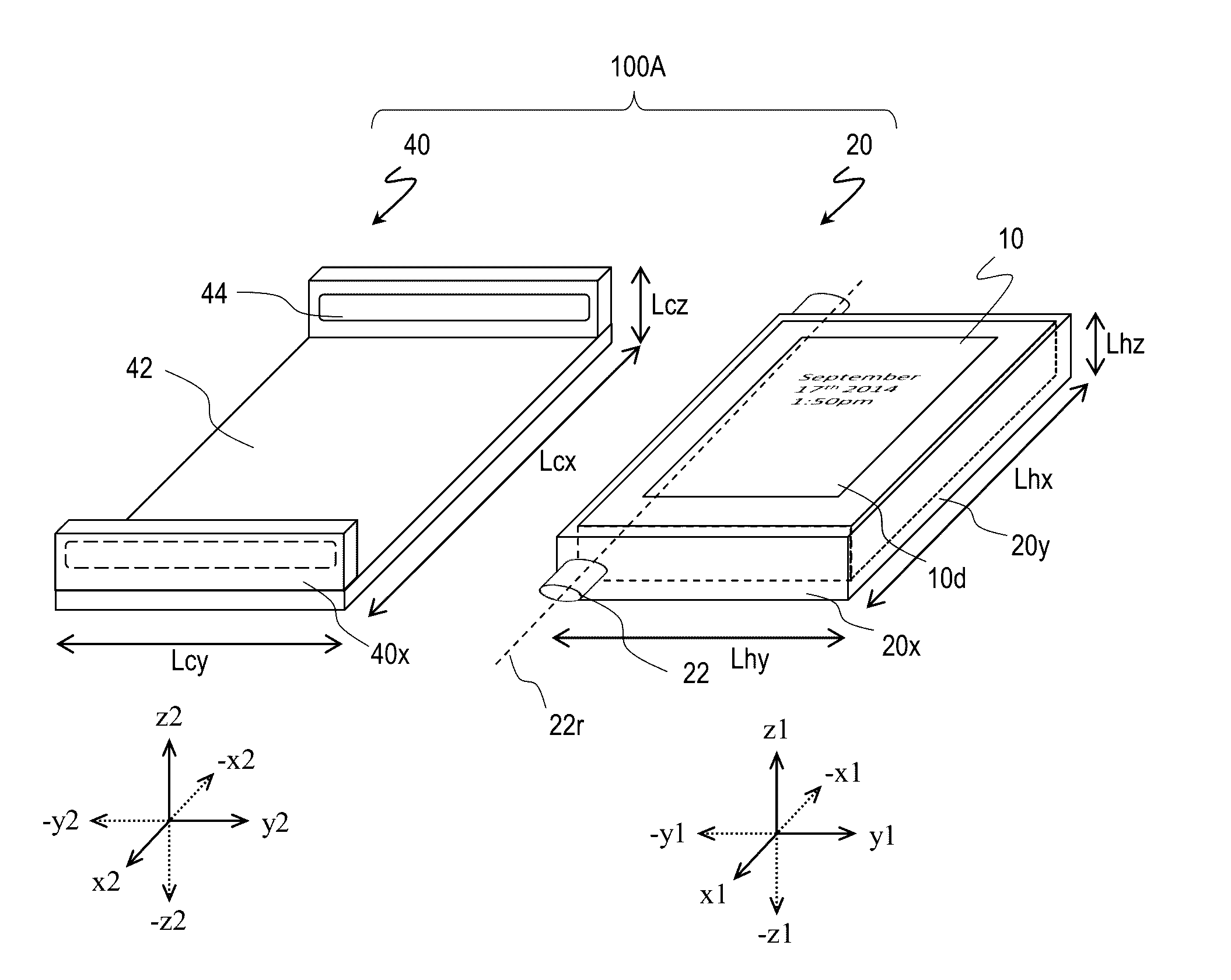
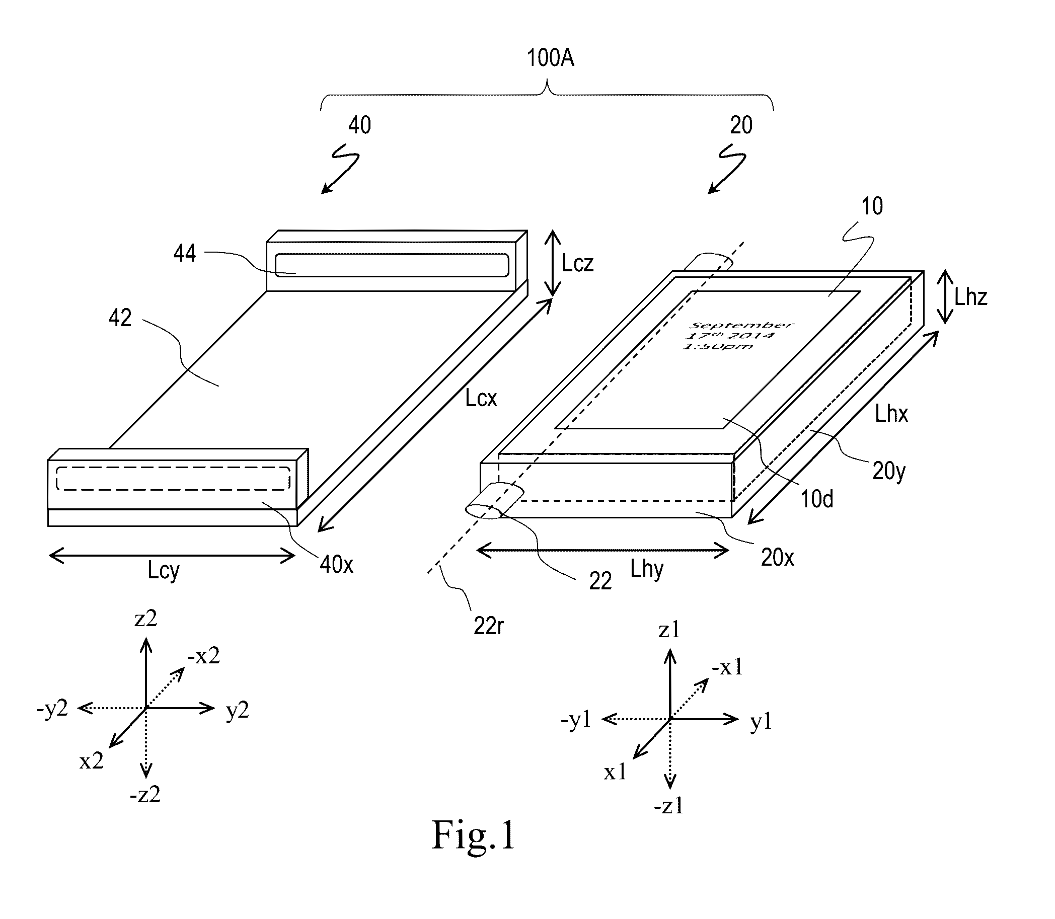
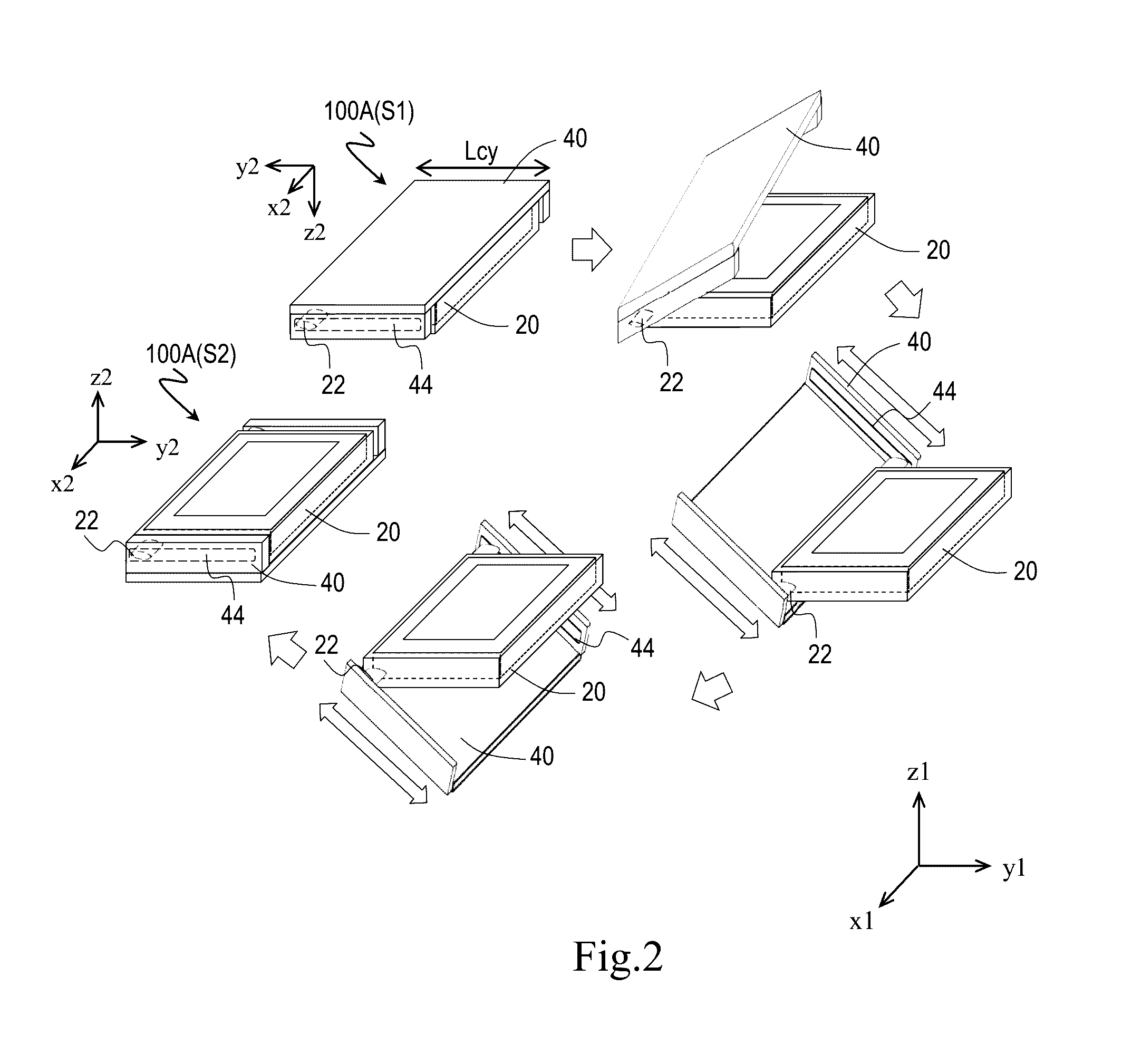
[0027]An electronic apparatus case 100A of Embodiment 1 according to the disclosure will be described with reference to FIGS. 1 to 3. FIG. 1 is a view schematically illustrating an electronic apparatus case 100A.

[0028]The electronic apparatus case 100A includes a holder 20 that holds an electronic and a cover 40 including a sheet-shaped cover 42 that covers a display surface 10d of the electronic apparatus 10. In the holder 20, an x1y1z1 orthogonal coordinate system, in which a direction that is orthogonal to the display surface 10d of the electronic apparatus 10 held in the holder 20 and away from the display surface 10d is a z1 axis, a direction that is orthogonal to the z1 axis and parallel to one side of the display surface 10d is a y1 axis, and a direction that is orthogonal to the y1 axis and the z1 axis is an x1 axis, is taken. In the cover 40, an x2y2z2 orthogonal coordinate system, in which a direction that coincides with the x1 axis is an x2 axis, a direction that is ortho...

embodiment 2

[0060]An electronic apparatus case 100B of Embodiment 2 according to the disclosure will be described with reference to FIG. 6. FIG. 6 is a view schematically illustrating the electronic apparatus case 100B. Hereinafter, in the electronic apparatus case 100B of the embodiment, points different from the electronic apparatus case of Embodiment 1 are mainly described. The same applies to the following embodiments.

[0061]In the electronic apparatus case 100B, a convex portion 22 has a main portion 21 and a fitting portion 23 that is fitted into a track 44. An area of a cross section of the fitting portion 23 parallel to the y1-z1 plane is greater than an area of a cross section of the main portion 21 parallel to the y1-z1 plane.

[0062]In the electronic apparatus case 100B, a cover 40 is slid with respect to a holder 20 along the track 44 and is rotated around a rotation axis 22r. Similar to the electronic apparatus case 100A, the electronic apparatus case 100B can perform opening and clos...

embodiment 3

[0071]An electronic apparatus case 100C of Embodiment 3 according to the disclosure will be described with reference to FIG. 8. FIG. 8 is a view schematically illustrating the electronic apparatus case 100C.

[0072]As illustrated in FIG. 8, the electronic apparatus case 100C further has a solar cell module 46 provided on a cover 42. The solar cell module 46 is exposed in each of a first state and a second state. The solar cell module 46 is provided, for example, on an outer surface of the cover 42.

[0073]The electronic apparatus case 100C is different from the electronic apparatus case of Embodiment 1 or Embodiment 2 described above in that the solar cell module 46 is further provided. The electronic apparatus case 100C may be the same as the electronic apparatus case of other embodiments except that the solar cell module 46 is further provided.

[0074]In the electronic apparatus case 100C, a cover 40 is slid with respect to a holder 20 along a track 44 and is rotated around a rotation a...


PUM


Abstract

An electronic apparatus case includes a holder holding an electronic apparatus and a cover covering a display. In the holder, when taking an x1y1z1 orthogonal coordinate system where a direction orthogonal to and away from the display surface is a z1 axis, and a direction parallel to a side of the display is a y1 axis. In the cover, when taking an x2y2z2 orthogonal coordinate system where a direction coinciding with the x1 axis is an x2 axis, and a direction orthogonal to the cover, and away from an inner surface of the cover is a z2 axis, the z1 axis coincides with the −z2 axis when the display is covered by the cover. The holder has a convex defining a rotation axis in the x1 axis direction and the cover has a track defining a gap extending in the y2 axis direction and storing the convex.

Description

BACKGROUND[0001]1. Field[0002]The present disclosure relates to a case and more particularly, to an electronic apparatus case. Moreover, in this specification, the electronic apparatus includes, for example, a mobile phone, a smart phone, a tablet PC, a portable game machine, a music player, an e-book terminal, an electronic dictionary, an electronic notebook, and the like.[0003]2. Description of the Related Art[0004]As electronic apparatuses have become more widespread, various electronic apparatus cases or covers have been developed. The electronic apparatus case (or cover) is, for example, intended to protect the electronic apparatus from impact or to avoid scratches of a display and / or a body of the electronic apparatus. Recently, a case or a cover having a function of not only protecting the electronic apparatus from impact or scratches but also charging the electronic apparatus has also been commercially available.[0005]According to the study of the present inventors, in the m...

Claims


Application Information

Patent Timeline
IPC IPC(8): A45C11/00H02S30/10A45F5/00
CPCA45C11/00A45F5/00A45C2011/003A45C2011/001A45C2011/002H02S30/10G06F1/1626H04B1/3888H04M1/0214H04M1/185G06F1/1616G06F2200/1634Y02E10/50
Inventor SHIBAHARA, MEHDIYOSHIE, TOMOHISASHIBATA, SATOSHIYAMANAKA, RYOHSUKE
Owner SHARP KK
Learn More