
Liquid ejecting head and liquid ejecting apparatus

a liquid ejecting head and liquid ejecting technology, which is applied in the direction of printing, inking apparatus, etc., can solve the problems of difficult to secure the mechanical strength of the liquid ejecting head, and achieve the effect of improving the mechanical strength of the components that form the space in which liquid is filled

Active Publication Date: 2016-09-29
SEIKO EPSON CORP
View PDF1 Cites 9 Cited by
  • Summary
  • Abstract
  • Description
  • Claims
  • Application Information

AI Technical Summary

Benefits of technology

The liquid ejecting head described in this patent has improved mechanical strength compared to previous versions. This is achieved by adding a beam-like portion on the inside of the housing unit, which increases the pressure and prevents adhesive from attaching to the beam. Additionally, a second beam-like portion may be added between the inner wall surfaces of the flow path substrate for even greater strength. The housing unit also has an inlet hole that allows for sufficient volume for the second space inside the housing unit. Overall, this design provides better performance and reliability for the liquid ejecting head.

Problems solved by technology

However, there is problem in that it is difficult to secure the mechanical strength of the liquid ejecting head due to the decrease in wall thickness.

Method used


Image

  • Liquid ejecting head and liquid ejecting apparatus
  • Liquid ejecting head and liquid ejecting apparatus
  • Liquid ejecting head and liquid ejecting apparatus

Examples


first embodiment

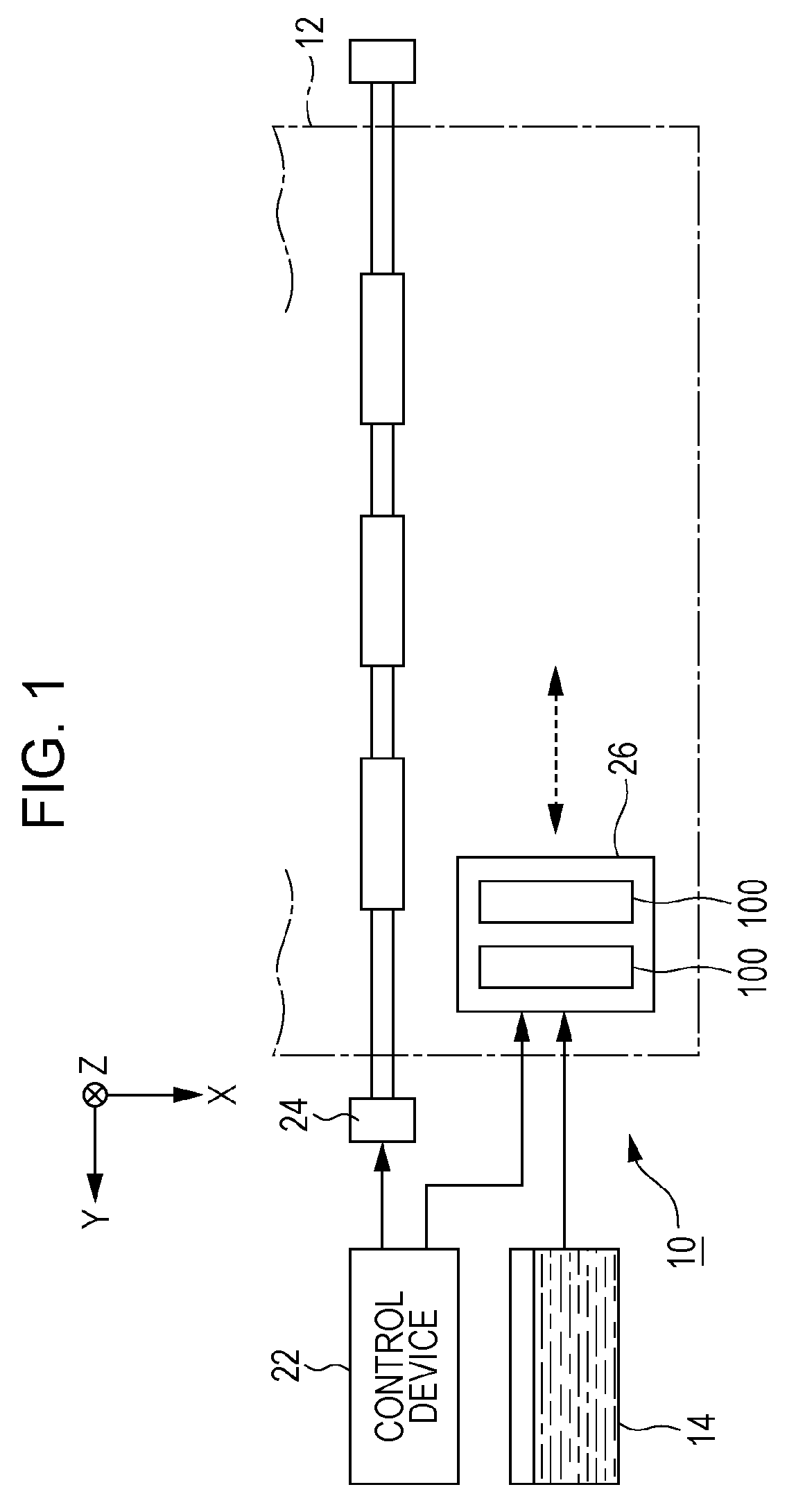
[0025]FIG. 1 is a partial schematic diagram of a printing apparatus 10 of an ink jet type according to a first embodiment of the invention. The printing apparatus 10 of the first embodiment is a preferable example of a liquid ejecting apparatus that ejects ink, which is an example of a liquid, onto a medium 12 (ejection target object) such as printing paper, and, as illustrated in FIG. 1, includes a control device 22, a transport mechanism 24, a carriage 26, and a plurality of liquid ejecting heads 100. A liquid container 14 (for example, a cartridge) that stores ink is mounted on the printing apparatus 10.

[0026]The control device 22 performs centralized control of the components of the printing apparatus 10. The transport mechanism 24 transports the medium 12 in the X direction under the control of the control device 22. Each of the liquid ejecting heads 100, under the control of the control device 22, ejects ink from a plurality of nozzles to the medium 12. The plurality of liquid...

second embodiment

[0057]A second embodiment of the invention will be described. Components of each of the examples given below that have the same operations and functions as those of the first embodiment are designated by the same reference symbols as used in the description of the first embodiment and detailed description thereof is omitted.

[0058]FIG. 8 is a cross-sectional diagram of one of the liquid ejecting heads 100 of the second embodiment and FIG. 9 is a plan view of one of the liquid ejecting heads 100 as seen from the negative Z direction side. In FIG. 9, an additional “1” is added after the reference symbols for components corresponding to the plurality of the nozzles N of the first line L1, and an additional “2” is added after the reference symbols for components corresponding to the plurality of the nozzles N of the second line L2. As illustrated in FIG. 9, in the top surface portion 42 of the housing unit 40 of the liquid ejecting heads 100 of the second embodiment, inlet holes 431 corr...

third embodiment

[0065]FIG. 10 is a cross-sectional diagram of one of the liquid ejecting heads 100 of the third embodiment. In the housing unit 40 of the third embodiment, as in the second embodiment illustrated in FIG. 9, two of the inlet holes 43 are arranged along the X direction and the inner wall surface of the liquid storage chambers SR include the inclined surfaces 47 (471 and 472). As illustrated in FIG. 10, the housing unit 40 of the liquid ejecting head 100 of the third embodiment includes an inclined portion 49, which is an outer wall surface inclined with respect to the first surface F1 (X-Y plane) of the flow path substrate 32. Specifically, the inclined portion 49 is a portion that is substantially parallel to the inclined surface 47 of the liquid storage chamber SR. Similarly to the first embodiment, the housing unit 40 of the third embodiment is formed of a resin material such as, for example, a liquid crystal polymer.

[0066]In the third embodiment, an opening portion 492 is formed i...


PUM


Abstract

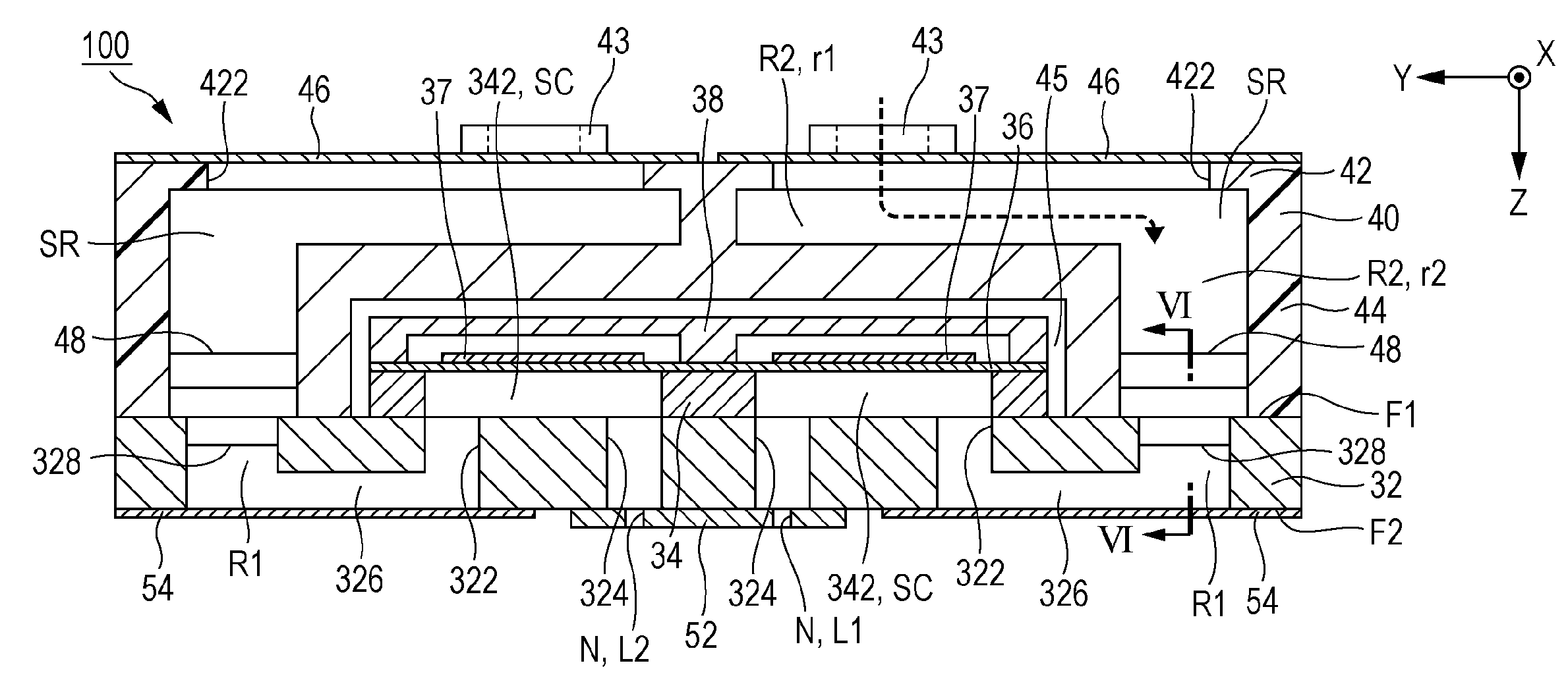
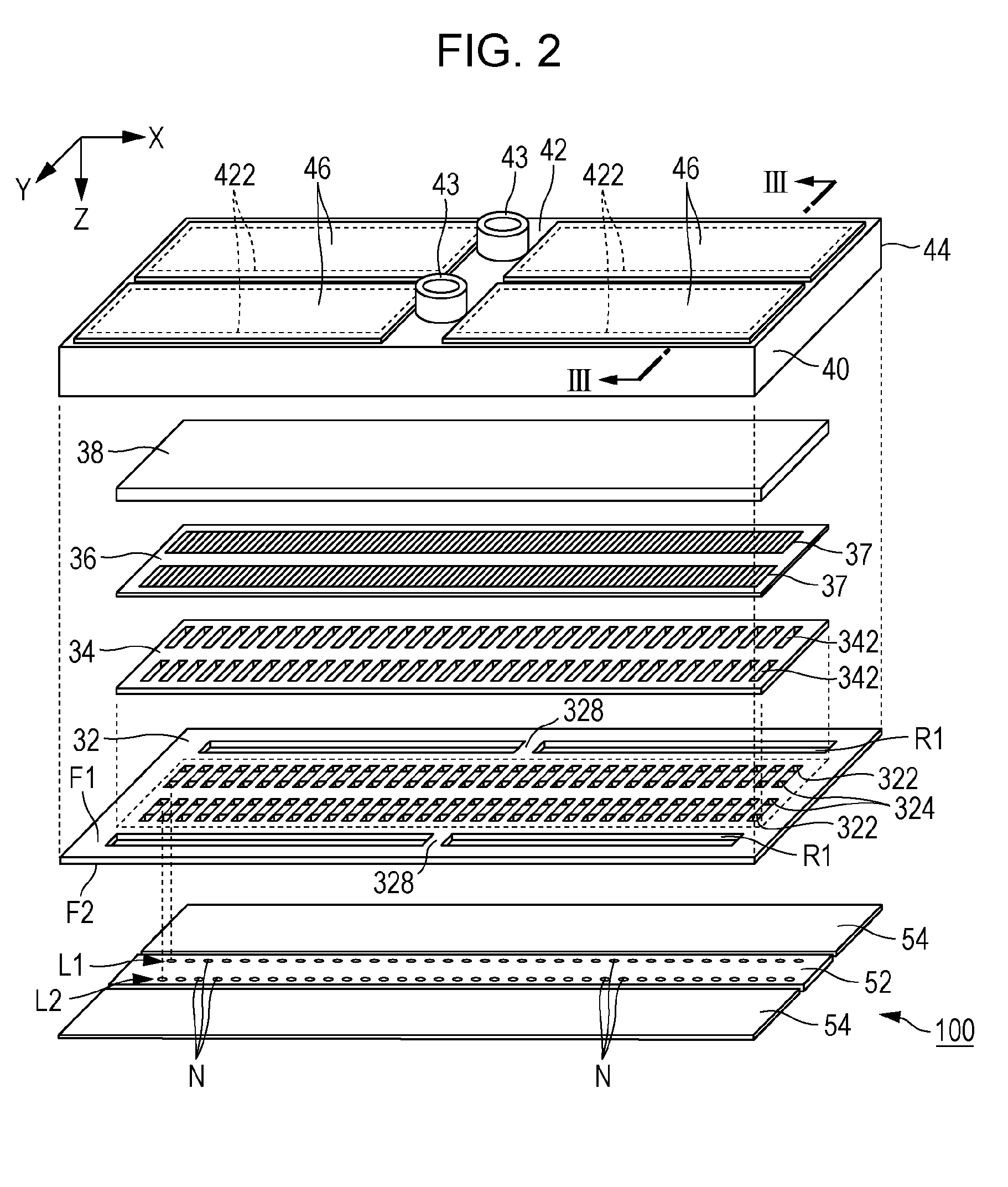
A liquid ejecting head includes a pressure chamber substrate in which a pressure chamber space is formed, a flow path substrate having a first surface on which the pressure chamber substrate is installed and a second surface that is on the opposite side to the first surface, and in which a first space, a supply hole that enables communication between the first space and the pressure chamber space, and a communication hole that communicates with the pressure chamber space are formed, a nozzle plate that is installed on the second surface and in which a nozzle that communicates with the communication hole is formed, a second space that is installed on the first surface and that communicates with the first space of the flow path substrate, a housing unit in which an opening portion that communicates with the second space is formed, a compliance unit that is flexible and installed on the second surface and that seals the communication hole and the first space, and a beam-like portion that extends between inner wall surfaces of the second space in the housing unit.

Description

[0001]The entire disclosure of Japanese Patent Application No: 2015-064143, filed Mar. 26, 2015 and 2016-020627, filed Feb. 5, 2016 are expressly incorporated by reference herein in its entirety.BACKGROUND[0002]1. Technical Field[0003]The present invention relates to a technology for ejecting liquid such as ink.[0004]2. Related Art[0005]To date, a liquid ejecting head has been proposed that ejects, from a nozzle, liquid such as ink that has filled a pressure chamber. For example, in JP-A-2013-129191, a structure is disclosed in which a liquid is supplied to a pressure chamber from a common liquid chamber that enables communication between a liquid chamber space portion formed in a communication substrate and a liquid chamber forming space portion of a unit case that fixes on the communication substrate.[0006]In order to reduce the size of a liquid ejecting head it is necessary to decrease the wall thickness of the unit case. However, there is problem in that it is difficult to secur...

Claims


Application Information

Patent Timeline
Patent Type & Authority Applications(United States)
IPC IPC(8): B41J2/14
CPCB41J2/1433B41J2/14233B41J2/055B41J2002/14241B41J2002/14306B41J2002/14419B41J2202/11
Inventor TAKINO, FUMIYAWATANABE, SHUNSUKEANEGAWA, KENTA
Owner SEIKO EPSON CORP
Learn More