Vasculature modeling

a vascular structure and model technology, applied in the field of vascular structure modeling, can solve the problems of inability to accurately model the vascular structure, inability to accurately predict the vascular structure, etc., to achieve the effect of reducing computation time, efficient evaluation, and small residual covering

Inactive Publication Date: 2016-09-29
SABANCI UNIVERSITY
View PDF1 Cites 4 Cited by
  • Summary
  • Abstract
  • Description
  • Claims
  • Application Information

AI Technical Summary

Benefits of technology

[0017]Preferably the vessel direction is determined by decomposing the four-dimensional tensor, which is fitted to the measurements, into its components. Thus, the determining the vessel direction preferably comprises decomposing the four-dimensional tensor into its components. For the purpose of this decomposition, a so-called Tucker decomposition is preferably utilized. Alternatively or additionally, the four-dimensional tensor is decomposed into its components by decomposing the four-dimensional tensor into at least one rank-1 term. Thereby the four-dimensional tensor representation is decomposed into an optional isotropic part, at least one rank-1 terms representing at least one individual fiber peak, as well as a small residual covering among others noise. With these techniques the four-dimensional tensor can be efficiently evaluated for vascular n-furcation modeling. The rank-1 approximation method thereby further reduces the computation time for modeling vascular structures in the sense of the present invention, while the Tucker decomposition proved to be even faster in the context of the present invention. It will be appreciated that several vessel directions may be determined for a given point, for example if a bifurcation is present at said given point.
[0018]In another preferred embodiment the method comprises the steps of selecting an initial seed point and estimating a vessel radius of the selected initial seed point. Preferably, the initiate the seed point is located on the at least one vessel. Accordingly, the extraction of the vessel tree starts from this initial seed point. The selection is preferably done by an operator or user, while the following tracing of the vessel is performed in a fast and automated manner. Accordingly, the inventive method is not only fast, but also provides an easy user interaction with a single seed selecti

Problems solved by technology

Vascular problems of human bodies can cause deadly medical events such as heart attacks and strokes.
The manual segmentation of vascular structures is an exhaustive task.
However, the presence of branchings

Method used


Image

  • Vasculature modeling
  • Vasculature modeling
  • Vasculature modeling

Examples


Embodiment Construction

[0025]In the following various aspects of the present invention are described more fully with reference to the accompanying drawings. The drawings are only for the purpose of illustrating preferred embodiments and are not to be construed as limiting the invention.

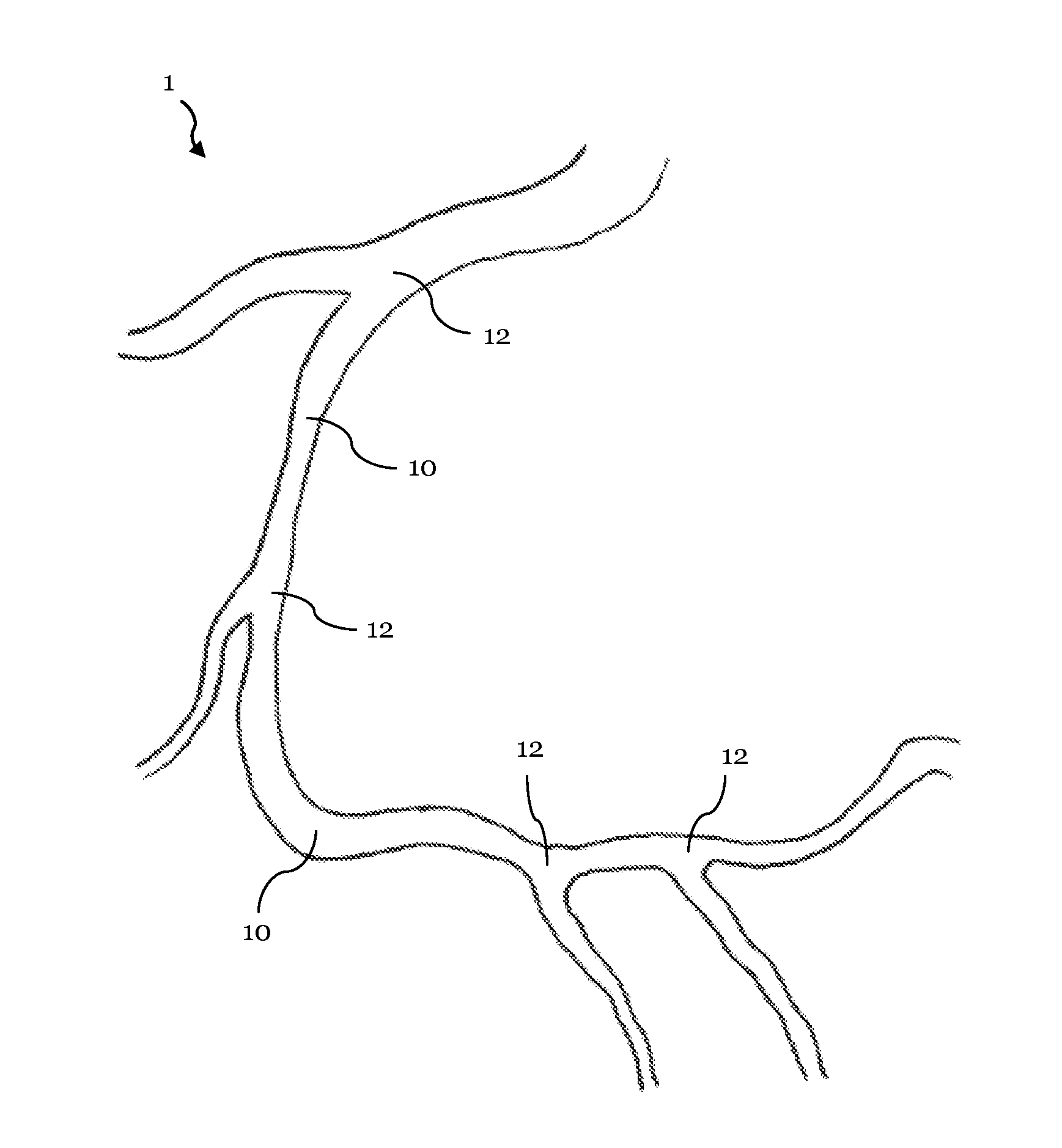
[0026]FIG. 1 illustrates a schematic representation of a vascular structure having several bifurcations;

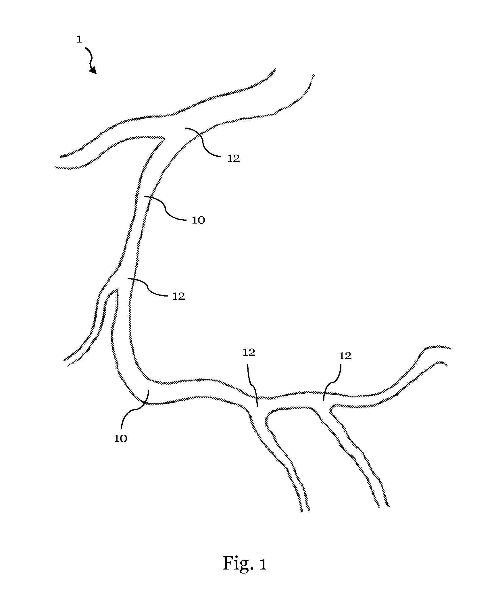
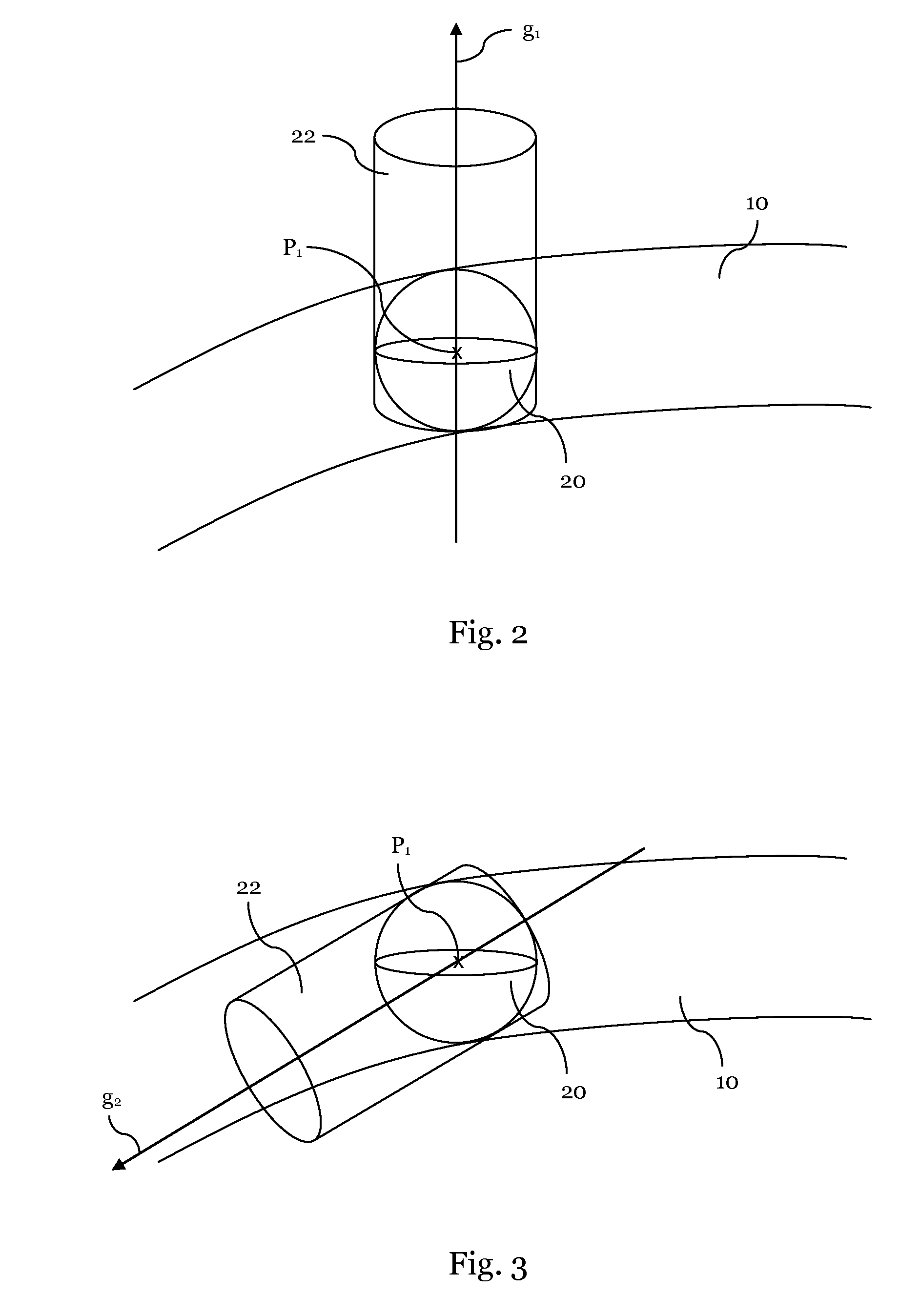
[0027]FIGS. 2 and 3 illustrate schematically a method for obtaining a directional measurement according to one embodiment;

[0028]FIGS. 4 and 5 illustrate schematically a method for obtaining a directional measurement according to another embodiment;

[0029]FIGS. 6 and 7 illustrate schematically a method for estimating a vessel thickness according to a further embodiment;

[0030]FIG. 8 illustrates an exemplary method for modeling vascular structures according to another embodiment;

[0031]FIG. 9 illustrates an exemplary method for modeling of vascular structures according to another embodiment;

[0032]FIG. 10 illustrates an exempla...


PUM


Abstract

The present invention relates to modeling of vascular structures, and in particular to extracting a vessel tree from medical-images of vascular anatomy. A respective method comprises among others the steps of providing an image of at least one vessel, obtaining multiple measurements from the image for a first point of the image, and fitting a four-dimensional tensor to the measurements. Based on said four-dimensional tensor fitted to the measurements, a vessel direction in a vessel tree is determined and a model of the vascular structures is generated based on at least the determined vessel direction.

Description

1. FIELD OF THE INVENTION[0001]The present invention relates to modeling of vascular structures, and in particular to extracting a vessel tree from medical images of vascular anatomy.2. TECHNICAL BACKGROUND[0002]Vascular problems of human bodies can cause deadly medical events such as heart attacks and strokes. The buildup of plaque inside a vascular system, for example, can lead to strokes or coronary heart disease. One important step for detecting and analyzing vessel anomalies and pathologies such as aneurysms, stenosis and plaques involves the extraction of vascular structures such as coronary and cerebral arteries.[0003]FIG. 1 illustrates a schematic portion of an exemplary vasculature 1. The illustrated vasculature 1, or vascular structure 1, can for example be part of an arterial or venous system. As can be seen in FIG. 1, the vasculature 1 having vessels 10 can feature furcations, such as the illustrated bifurcations 12. It is known that vascular structures can also have mor...

Claims


Application Information

Patent Timeline
IPC IPC(8): G06T7/00G06T17/20G06T5/00A61B5/02
CPCG06T7/0012A61B5/02007G06T17/20G06T2207/30101G06T7/0051G06T7/0079G06T5/003G06T2207/10092G06T2207/30172G06T7/13G06T7/162
Inventor UNAL, GOZDECETIN, SUHEYLA
Owner SABANCI UNIVERSITY
Why Eureka
Try Eureka