Method for operating a MIMO radar

a technology of mimo radar and operating method, which is applied in the direction of using reradiation, measuring devices, instruments, etc., can solve the problems of inability to use at all, system can only carry out inaccurate angle estimates, and the doa estimate of such a system can be poorer than the utilization of an individual transmitting antenna

Active Publication Date: 2014-11-27
ROBERT BOSCH GMBH
View PDF4 Cites 40 Cited by
  • Summary
  • Abstract
  • Description
  • Claims
  • Application Information

AI Technical Summary

Benefits of technology

[0010]The object of the present invention is therefor...

Problems solved by technology

Depending on the time multiplex schema used, and on the disposition of the antennas, a DOA estimate of such a system can in fact be poorer than utilization of an individual transmitting antenna.
The proposed system can carry out only inaccurate angle estimate...

Method used


Image

  • Method for operating a MIMO radar
  • Method for operating a MIMO radar
  • Method for operating a MIMO radar

Examples


Embodiment Construction

[0047]In order to allow the advantages of MIMO radar to be utilized, the transmitted signals that are used should preferably be orthogonal to one another, i.e. should exhibit no dependencies on one another. There are in principle three possibilities for this, but all have specific disadvantages:[0048]code multiplexing in fast or slow time has a high level of technical complexity and only limited orthogonality;[0049]frequency multiplexing produces a wavelength-dependent phase shift and Doppler shift;[0050]time multiplexing, in a context of object motions between switchovers, results in different phases, complicating the subsequent angle estimate.

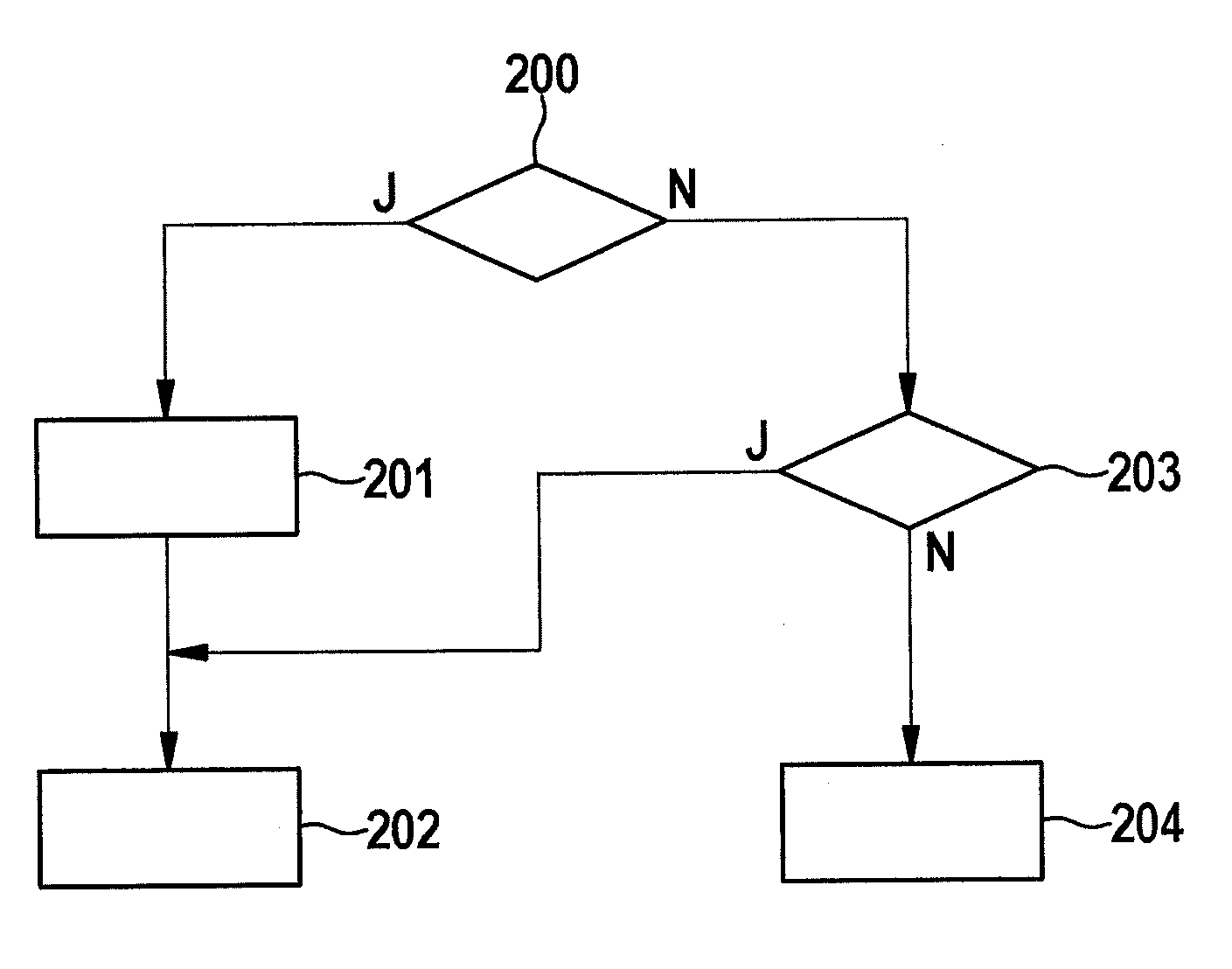
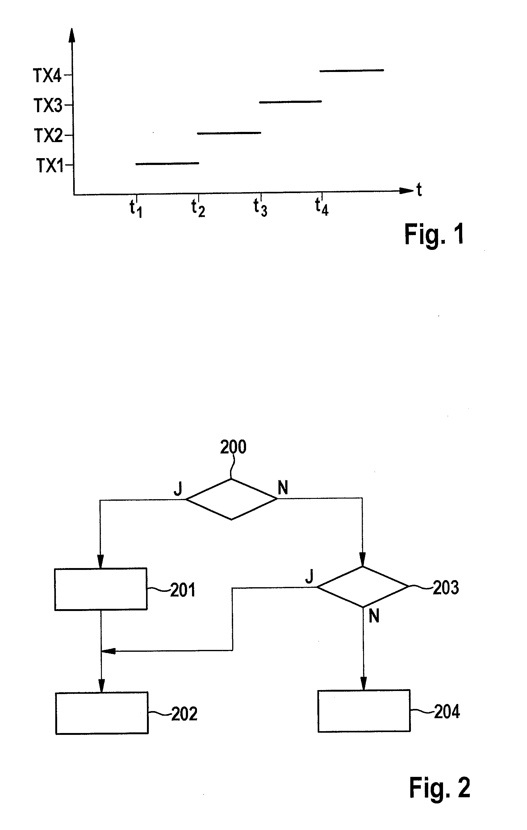
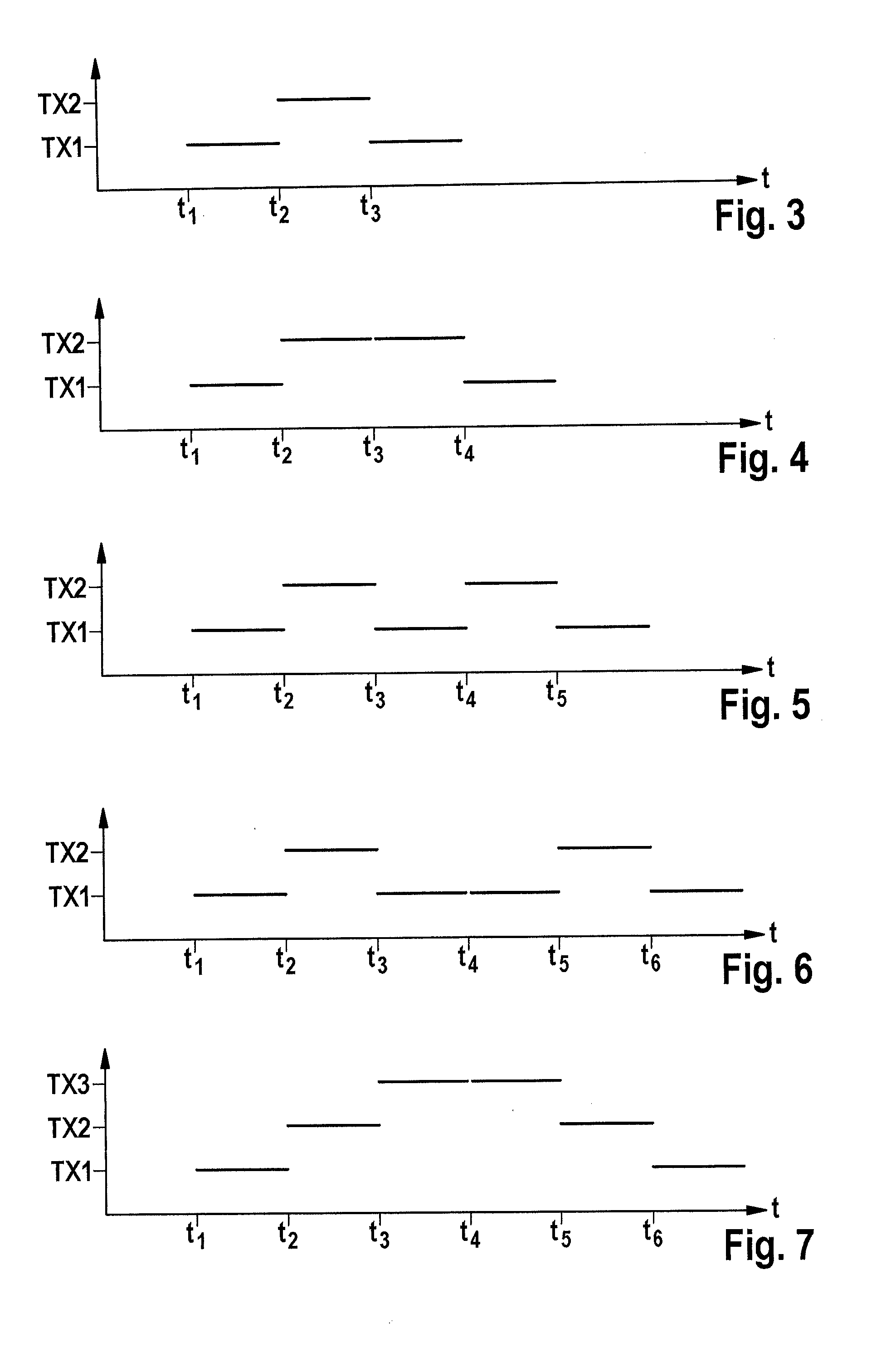
[0051]Closer consideration will be given hereinafter exclusively to the time multiplexing method, since it can be implemented relatively simply in terms of circuit technology and is thus economical. The present invention proposes a time multiplex switching concept which is notable for the fact that object motions between switchovers of the tr...


PUM


Abstract

In a method for operating a MIMO radar, an influence of an object motion on an angle estimate is substantially eliminated, and a time multiplex schema having a transmission sequence and transmission instants of transmitters of the MIMO radar is identified by optimizing the following mathematical relationship:
d _ pulses , opt = arg max d _ pulses [ Var S ( d _ pulses ) - ( Cov S ( d _ pulses , t ) ) 2 / Var S ( t _ ) ]
in which: dpulses,opt is optimized positions of the transmitters in the sequence in which they transmit; dpulses is positions of the transmitters in the sequence in which they transmit; t is transmission instants; VarS is sample variance; and CovS is sample covariance.

Description

BACKGROUND OF THE INVENTION[0001]1. Field of the Invention[0002]The invention relates to a method for operating a MIMO radar, e.g., a use of a MIMO radar in the automotive sector.[0003]2. Description of the Related Art[0004]Radar systems are used in motor vehicles in order to determine distances and relative velocities of objects in the vicinity of the motor vehicles. The aforesaid radar systems can be used in order to implement convenience functions (for example adaptive cruise control [ACC]) and safety functions (for example to warn the driver in critical situations or to cause maximum braking when a collision can no longer be avoided).[0005]For these applications, the distance and the relative velocity of the objects, and the angle of the reflected radar waves, must be precisely identified. An exact estimate of the angle, or direction of arrival (DOA), should in particular be carried out for this purpose. The angle to be estimated can be an azimuth angle and / or an elevation angle...

Claims


Application Information

Patent Timeline
IPC IPC(8): G01S13/02G01S13/931
CPCG01S13/02G01S7/35G01S13/003G01S13/42G01S13/931G01S7/4008G01S13/343G01S7/4034G01S7/403
Inventor SCHOOR, MICHAELKUEHNLE, GOETZRAMBACH, KILIANLOESCH, BENEDIKT
Owner ROBERT BOSCH GMBH
Why Eureka
Try Eureka