Optional Device for Electrical Machine, and Electrical Machine

a technology of optional devices and electrical machines, applied in the direction of electrical apparatus casings/cabinets/drawers, instruments, separation processes, etc., can solve problems such as cost increas

Active Publication Date: 2016-09-29
KONICA MINOLTA INC
View PDF16 Cites 5 Cited by
  • Summary
  • Abstract
  • Description
  • Claims
  • Application Information

AI Technical Summary

Benefits of technology

[0011]According to one aspect of the present invention, an optional device is for an electrical machine. The optional device is mountable to the electrical machine without electrical connection to the electrical machine. The optional device includes a duct, an air flow sensor, an air purifier, and a controller. Through the duct, an air flow containing an exhaust gas from the electrical machine is guided. The air flow sensor is configured to detect presence or absence of the exhaust gas from the electrical machine. The air purifier is configured to purify the exhaust gas and discharge the purified exhaust gas into an atmosphere. The controller is configured to control an operation of the air purifier based on an output from the air flow sensor.
[0012]According to another aspect of the present invention, an electrical machine includes a

Problems solved by technology

Providing the interface le

Method used


Image

  • Optional Device for Electrical Machine, and Electrical Machine
  • Optional Device for Electrical Machine, and Electrical Machine
  • Optional Device for Electrical Machine, and Electrical Machine

Examples


Embodiment Construction

[0033]The embodiments will now be described with reference to the accompanying drawings, wherein like reference numerals designate corresponding or identical elements throughout the various drawings.

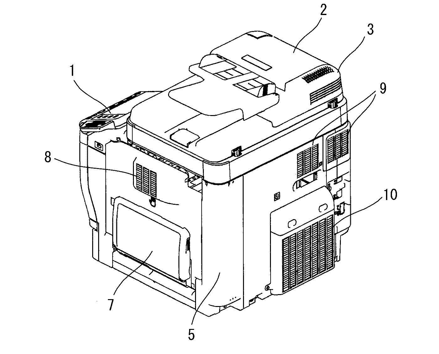
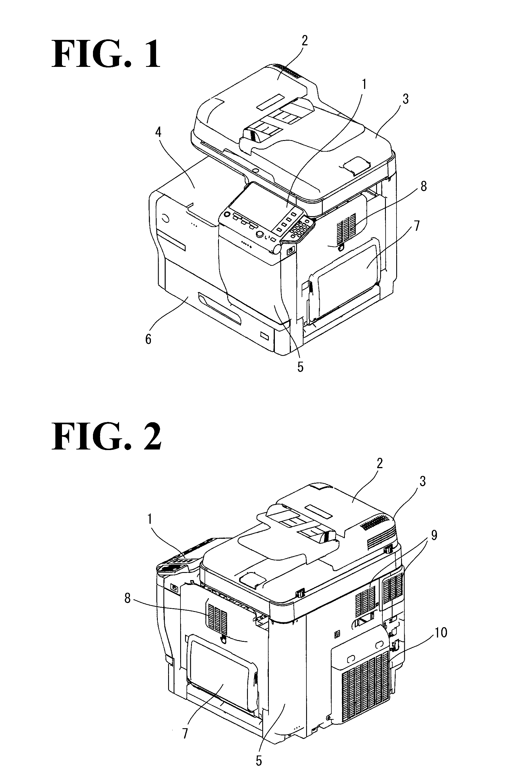
[0034]FIGS. 1 and 2 are perspective views of a multi-purpose machine, which is an exemplary image forming apparatus to which the optional device according to this embodiment is discretely mounted. FIG. 1 is a perspective view of the multi-purpose machine as seen from a forward right direction, and FIG. 2 is a perspective view of the multi-purpose machine as seen from a rearward right direction. The following description, as necessary, may refer to particular directions and positions using terms such as “left and right”, “up and down (above and below or under)”, and “front and rear”. These terms are based on the front view of the image forming apparatus, which is an elevational view of the front surface, on which an operation panel 1 is disposed.

[0035]The multi-purpose machine includes th...


PUM

PropertyMeasurementUnit
Timeaaaaaaaaaa

Abstract

An optional device is for an electrical machine. The optional device is mountable to the electrical machine without electrical connection to the electrical machine. The optional device includes a duct, an air flow sensor, an air purifier, and a controller. Through the duct, an air flow containing an exhaust gas from the electrical machine is guided. The air flow sensor is configured to detect presence or absence of the exhaust gas from the electrical machine. The air purifier is configured to purify the exhaust gas and discharge the purified exhaust gas into an atmosphere. The controller is configured to control an operation of the air purifier based on an output from the air flow sensor.

Description

CROSS-REFERENCE TO RELATED APPLICATIONS[0001]The present application claims priority under 35 U.S.C. §119 to Japanese Patent Application No. 2015-63277, filed Mar. 25, 2015. The contents of this application are incorporated herein by reference in their entirety.BACKGROUND OF THE INVENTION[0002]1. Field of the Invention[0003]The present invention relates to an optional device for an electrical machine and to an electrical machine.[0004]2. Discussion of the Background[0005]Electrical machines such as image forming apparatuses emit exhaust gases that contain ultrafine particles (UFPs) of siloxane, which results from heating of silicon, or hydrocarbon, which results from melting of toner at high temperatures. In recent years, stricter regulations have been imposed on ultrafine particles. This requires the electrical machines to use a filter or a similar device to collect ultrafine particles in the exhaust gas and to discharge purified air to the atmosphere. Newly developed electrical ma...

Claims


Application Information

Patent Timeline
IPC IPC(8): H05K5/02B01D46/44B01D46/46B01D46/00
CPCH05K5/0213B01D46/46B01D46/444B01D46/0002G03G21/206G03G2221/1645G03G2221/1696
Inventor NARAHASHI, HIDEKIASAOKA, SHOGOKARAKAMA, SHOTOMODA, YASUAKIMATSUI, NAOKI
Owner KONICA MINOLTA INC
Why Eureka
Try Eureka