Sliding and rotatable vented damper for the control of a fluid through a conduit

a technology of venting damper and fluid flow, which is applied in the direction of venting valves, mechanical devices, functional valve types, etc., can solve the problems of obstructing the flow of fluid, many problems within the conduit, and most obstruction of the flow of fluid

Active Publication Date: 2021-06-17
WARRENTECH
View PDF0 Cites 1 Cited by
  • Summary
  • Abstract
  • Description
  • Claims
  • Application Information

AI Technical Summary

Benefits of technology

[0007]When the fixed plate and slide plate are in a closed position, the fixed plate and slide plate are in a plane perpendicular to the flow of a fluid in a conduit. The opening of the slide plate are misaligned with the opening of the fixed plate such that a negligible amount of fluid passes through the openings. The slide plate can then be adjusted to an open position by sliding the slide plate relative to the fixed plate. This movement allows for the opening of the slide plate to begin to align with the openings of the fixed plate. As the openings of the slide plate and fixed plate become more aligned, a greater amount of flow is allowed to pass through the openings. Once the slide plate is moved to its full open position, the opening of the slide plate and the opening of the fixed plate are in full alignment, allowing for maximum flow through the openings.

Problems solved by technology

These systems usually involve the use of apparatuses that somehow obstruct the flow of the fluid.
This causes the most obstruction of the flow of the fluid.
However, setting one or more blades at such a position creates many problems within the conduit.
This results in a negative pressure behind the blade.
Further, this often causes the flow of the fluid to become turbulent and generate noise within the conduit.
The non-laminar flow creates higher energy costs due to inefficient heat transfer, and the noise may become a nuisance.

Method used


Image

  • Sliding and rotatable vented damper for the control of a fluid through a conduit
  • Sliding and rotatable vented damper for the control of a fluid through a conduit
  • Sliding and rotatable vented damper for the control of a fluid through a conduit

Examples


Embodiment Construction

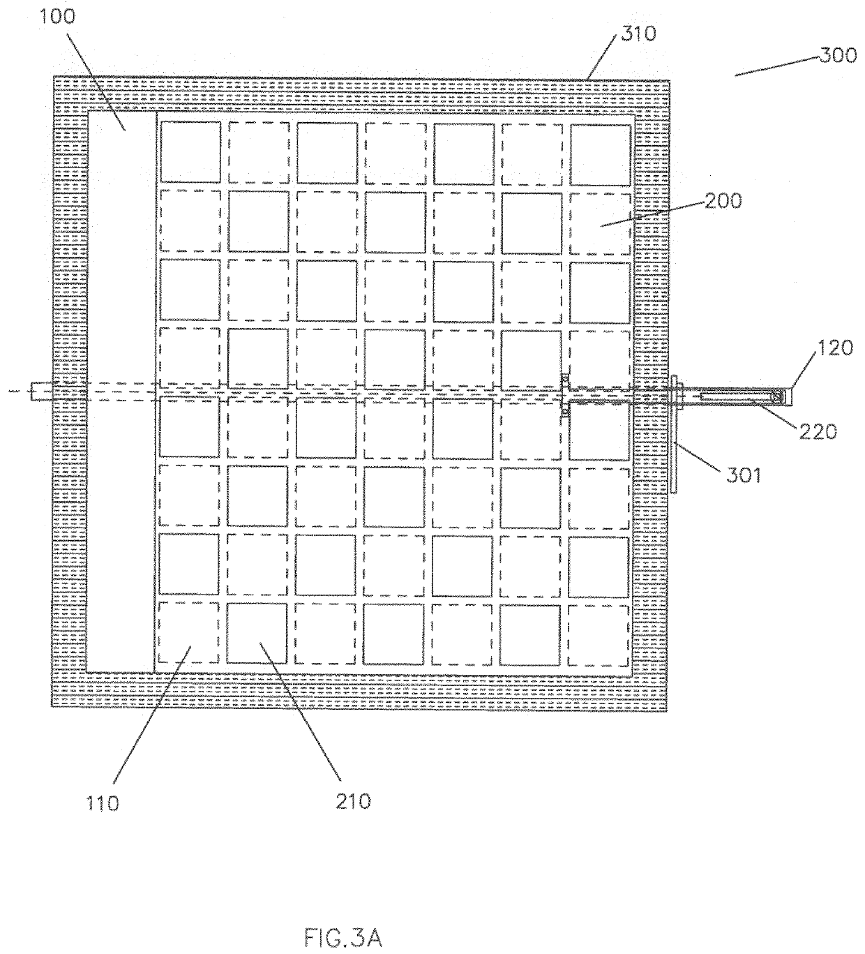
[0020]Implementations of the invention provide a damper apparatus adapted to control the flow of fluids or semi-solid materials through ductwork or any other type of conduit 600.

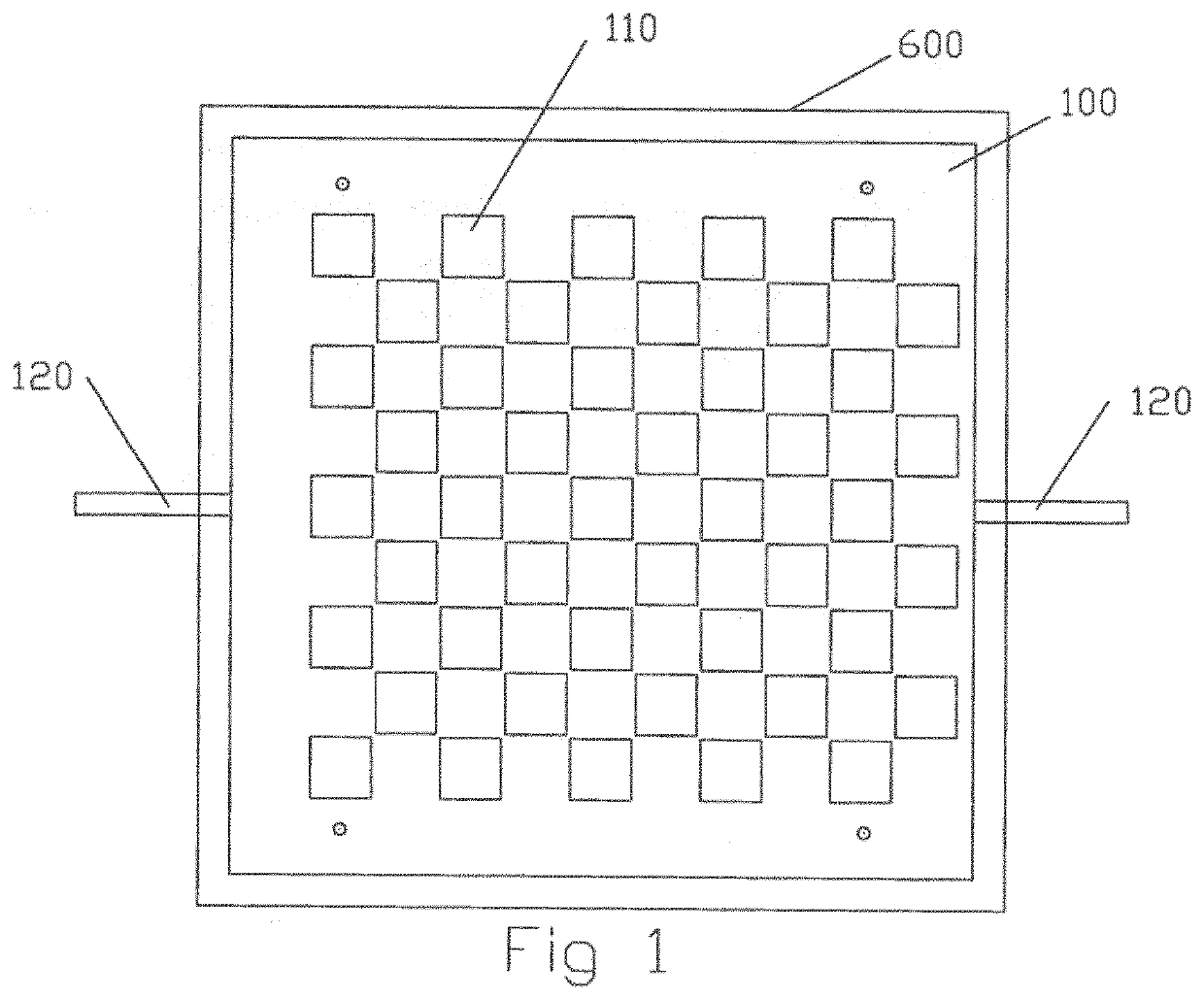
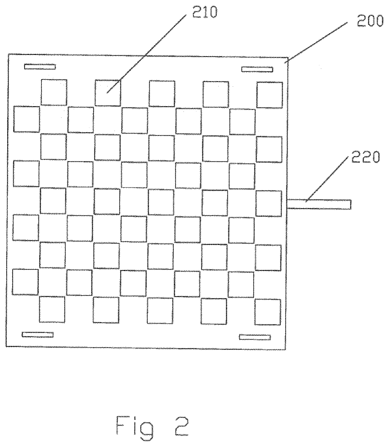
[0021]FIGS. 1 and 2 illustrate a fixed plate 100 and a slide plate 200, respectively, that may be used in an embodiment of the damper apparatus (explained in further detail below with respect to FIGS. 3A-3C). Referring to FIG. 1, the fixed plate 100 is shown having a substantially flat body and one or more openings 110 through the body. In the example embodiment, the shape of the fixed plate 100 is rectangular; however, the fixed plate 100 may be any shape that substantially corresponds with the cross section of any conduit 600 of any shape, including round, square, obround, rectangular, or any other variation of a shaped outlet.

[0022]The one or more openings 110 of the fixed plate 100 may have a coordinated size, shape, or pattern of arrangement; however, the one or more openings 110 of the fixed plate 100 ...


PUM


Abstract

The invention provides an apparatus for adjusting the flow of a fluid within a conduit, comprising a slide plate with a flat body and a fixed plate with a flat body. The slide plate and fixed plate have openings on their bodies. At a fully closed position, the openings of the slide plate do not substantially overlap with the openings of the fixed plate. By rotation of an actuator shaft and drive pin disposed thereon, the slide plate may move relative to the fixed plate, whereby the openings of the slide plate begin overlapping with the opening of the fixed plate, thereby allowing flow of fluid through the openings. Sequentially or independently from the movement of the slide plate, rotation of the actuator shaft may cause the fixed plate to rotate relative to the walls of the conduit, whereby flow of fluid may pass through the opening between the conduit and fixed plate assembly.

Description

FIELD OF THE INVENTION[0001]The present invention relates to an apparatus for controlling the flow of a fluid through a conduit. More specifically, the apparatus may be adjusted to increase the level of flow of the fluid by engaging sliding and rotating mechanisms.BACKGROUND[0002]Damper systems allow for flow of a fluid in a conduit to be controlled or set a desired level. These systems usually involve the use of apparatuses that somehow obstruct the flow of the fluid. These systems are used in many settings, for example and without intending to limit the scope of the present invention, to control the flow of air in conduits in heating, ventilation, and air conditioning (HVAC) applications. Many of these apparatuses are adjustable, such that different flow levels may be selected via the same apparatus. At times, it is preferable to a have a system which is able to adjust the level of flow quickly and easily without the need to access the conduit itself.[0003]One configuration in whi...

Claims


Application Information

Patent Timeline
Patent Type & Authority Applications(United States)
IPC IPC(8): F16K1/16F16K24/04F16K24/02
CPCF16K1/165F24F13/12F16K24/02F16K24/04F16K1/221F16K1/222F16K1/223F16K1/526F16K1/54F16K3/0209F24F13/14
Inventor KELLEY, WINFIELD L.GREENOUGH, DAVID J.
Owner WARRENTECH
Why Eureka
Try Eureka