Hydrodynamic torque converter

a torque converter and hydrodynamic technology, applied in the direction of fluid couplings, gearings, couplings, etc., can solve the problem of not being able to achieve relative motion between the freewheel inner ring and the hollow stator sha

Inactive Publication Date: 2006-11-16
LUK LAMELLEN & KUPPLUNGSBAU BETEILIGUNGS KG
View PDF9 Cites 2 Cited by
  • Summary
  • Abstract
  • Description
  • Claims
  • Application Information

AI Technical Summary

Benefits of technology

[0011] In comparison to a conventional freewheel inner ring, the freewheel inner ring designed in accordance with the present invention may able to be manufactured without a collar and without requiring any additional outlay. It may be manufactured, for example, in a compression-molding process, such as reverse extrusion, or in a sintering process. The amount of additional material required for the internal shoulder may be very negligible and may be less than that which would be have to be added for an external collar on the hollow stator shaft. Moreover, the internal shoulder may not affect the flow cross-section between the pump neck and the hollow stator shaft. Also, it may not be possible for any relative motion to come about between the freewheel inner ring and the hollow stator shaft; and the position of the freewheel inner ring may not need to be specified already at the initial design stage.

Problems solved by technology

Also, it may not be possible for any relative motion to come about between the freewheel inner ring and the hollow stator shaft; and the position of the freewheel inner ring may not need to be specified already at the initial design stage.

Method used


Image

  • Hydrodynamic torque converter
  • Hydrodynamic torque converter

Examples


Embodiment Construction

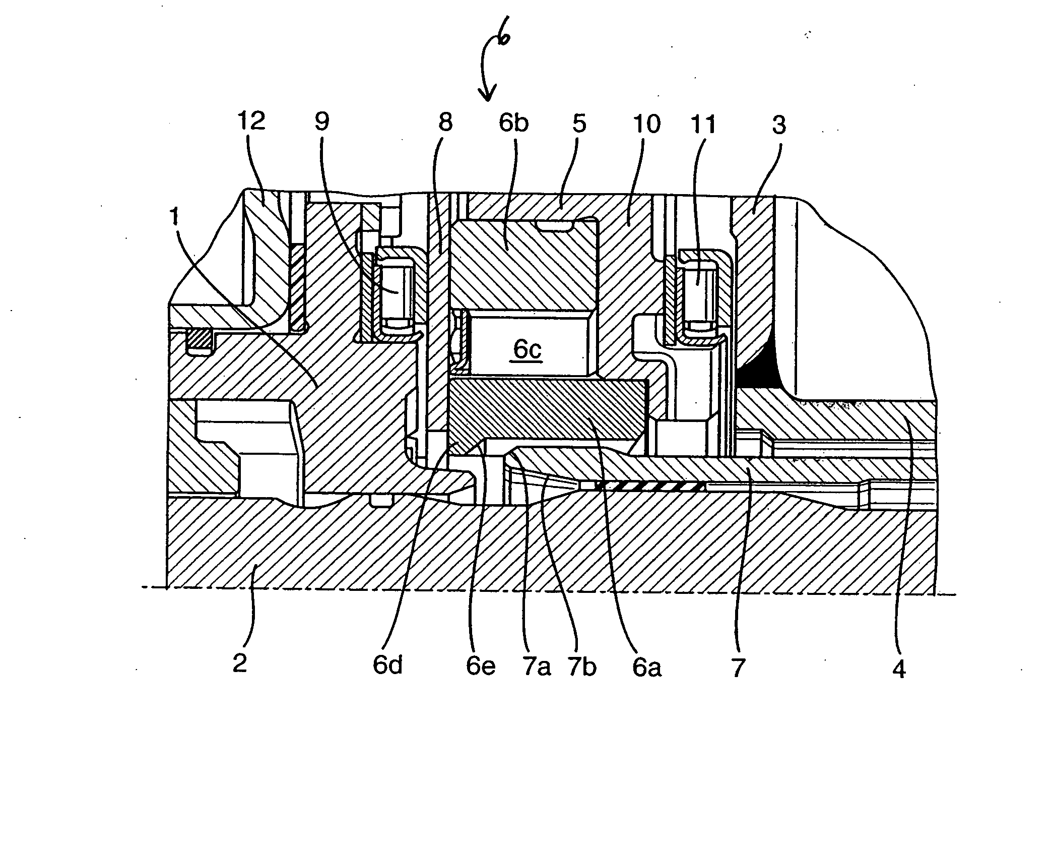
[0015] In FIG. 1, the cut-away portion reveals a turbine hub 1 of an only partially represented torque converter, which, radially outwardly, supports a turbine, whose torque is transmitted via turbine hub 1 to transmission input shaft 2 and, thus, to a transmission. Schematically illustrated opposite turbine hub 1 is an outer shell 3 of an impeller, from which a pump neck 4 extends in the direction of the transmission and is rotatably and sealingly supportable in the transmission housing. Outer shell 3 of the impeller is welded to an engine-side housing shell 12 of the torque converter to form a toroidal-type housing which encloses the torque converter in a fluid tight manner, pump neck 4 terminating at the transmission housing. Disposed nonrotatably between outer shell 3 of the impeller and an inner shell of the impeller are vane segments, which make up the impeller, which, in response to rotation, drive a fluid flow inside of the torque converter which, in turn, drives the turbine...


PUM


Abstract

A hydrodynamic torque converter includes a housing-mounted impeller, a turbine that is torsionally fixed with respect to a transmission input shaft, and a stator braced by an axial bearing and supported on a freewheeling device between the impeller and the turbine. When attaching the torque converter to a transmission, the freewheel inner ring of the freewheel being slid in a torsionally fixed manner onto a non-rotating hollow stator shaft that is attached to the transmission housing, on the end face facing away from the hollow stator shaft, the freewheel inner ring has an internal shoulder which forms an assembly limit stop for the unattached end of the hollow stator shaft.

Description

[0001] This application claims the benefit of German Patent Application No. 10 2005 018 223.2 filed Apr. 20, 2005 and hereby incorporated by reference herein. [0002] The present invention provides a hydrodynamic torque converter, which has a housing-mounted impeller, a turbine that is torsionally fixed with respect to a transmission input shaft, and a stator braced by an axial bearing and supported on a freewheeling device between the impeller and the turbine, when attaching the converter to a transmission, the freewheel inner ring of the freewheel being slid in a torsionally fixed manner onto a non-rotating hollow stator shaft attached to the transmission housing. BACKGROUND [0003] Hydrodynamic torque converters are primarily used for transmitting a torque from a crankshaft of an engine to a transmission input shaft. Within one housing, they accommodate a housing-mounted impeller, a turbine, and a stator. The torque converter is integrated in the hydraulic circuit of the transmissi...

Claims


Application Information

Patent Timeline
Patent Type & Authority Applications(United States)
IPC IPC(8): F16D33/00
CPCF16H2041/246F16H41/24
Inventor MAIENSCHEIN, STEPHAN
Owner LUK LAMELLEN & KUPPLUNGSBAU BETEILIGUNGS KG
Why Eureka
Try Eureka