
Treadmill

a treadmill and treadmill technology, applied in the field of treadmills, can solve the problems of high growth in the cost of health care for society, fatigue of joints or bones, and deterioration of diet of many peopl

Active Publication Date: 2016-10-06
MOSER GEORGE
View PDF28 Cites 57 Cited by
  • Summary
  • Abstract
  • Description
  • Claims
  • Application Information

AI Technical Summary

Benefits of technology

The present patent describes improvements to treadmills in terms of deck suspension, orientation adjustability, and electronic control. The treadmill includes a rigid frame with a front and rear roller, and a flexible belt wrapped around the rollers. The deck is fully suspended relative to the frame by air suspension elements. The air suspension elements may include a dampening mechanism to control air pressure within the elements. The treadmill also includes an incline mechanism and a decline mechanism for adjusting the treadmill's angle. The patent also describes an external digital interface for controlling the treadmill's motion using a mobile phone, tablet, or computer. The technical effects of the patent include improved suspension, better orientation adjustability, and improved control and user experience.

Problems solved by technology

Simultaneously, the diet of many people has deteriorated, with ensuing obesity, diabetes, heart disease and many other modern diseases.
This lifestyle has also led to high growth in the cost of health care for society.
However the treadmill, which has been around for many decades, still has many unresolved shortcomings that discourage a wider use.
a) Impact: potential damage to joints because of repetitive impact, which eventually causes fatigue failure to joints or bones. Fatigue is a well-known effect in engineering and well described by the Woehler curve, which causes failure of mechanical components due to stresses that can be well tolerated if they happen occasionally but will lead to failure if applied repetitively; an analogy would be bending a wire a couple of times, which probably will not cause damage to the wire, but if that is repeated back and forth many times, it is likely that the wire will break. The legs can be subjected to hundreds of thousands of repetitive impacts on a conventional treadmill, so fatigue is a very real issue in these machines; and
b) boredom during usage of the treadmill, which leads to users giving up and not coming back to the treadmill, which often becomes a dust collector in a household.
There have been many unsuccessful attempts to resolve the above issues, which continue to plague even the latest, most advanced treadmills.
The proposed structure has issues of excessive complexity and high cost, as well as non-adjustability, meaning that all users are treated equally, despite differences in size, weight, age, gender, health condition, prior injuries, and the like.
This arrangement provides very limited and partial dampening at best, because the rear of the treadmill is sitting undampened on a rigid steel bar.
In addition, this system is also non-adjustable and non-controllable.
However, the complexity, cost and weight of such a system make it impractical.
In addition, a user would have to stop the treadmill and climb underneath to do any adjustments, and repeat this trial and error procedure until the right point is reached, which is not something most users would be willing to do.
This arrangement is susceptible to wear, noise, potential cuts and punctures, air leaks, high cost and short useful life of the bladders.
It is believed to be an impractical approach that has never reached wide scale commercial implementation, likely for the reasons just mentioned.
That is a more practical approach that has been used for many years, but of course it lacks adjustability.
A major disadvantage is that it dampens only the front of the treadmill, while the rear wheels sit undampened directly on the floor (which is rigid and generates impact reaction forces that may continue to hit the user).
A second major issue with that proposed configuration is that the full weight of the treadmill upper structure (including its heavy metal frame structure, deck, stepping board, belt and other components plus user weight) has to be carried by the air springs.
That makes it necessary to use relatively stiff air springs with high internal air pressure, and the ability to dampen the user is severely limited (the air springs have to be designed to carry the machine weight plus the person, not just the person).
The result is a relatively stiff ride with significant user impact.
A further problem in the '160 Patent is the unnatural pivoting motion of the user when potentially using such a machine.
Instead of experiencing the normal, primarily vertical “ups and downs” of a walk, the user would be subject to a repetitive circular motion around the contact point of the rear wheel on the floor, which may feel unnatural and potentially uncomfortable or dizzying.
Another issue in '160 Patent is the absence of a complete dampening system.
The undampened air springs can lead to an uncomfortable ride on the treadmill.
Similar foam or polymer layer approaches have been used for many years, but they provide limited cushioning and very limited or no adjustability to different users.
Another major problem with treadmills is their boring nature which makes many users abandon their exercise program.
Despite all those ideas and concepts, the problem of boredom remains largely unsolved and many users quit the use of the treadmill after a short period of time due to boredom.
In some embodiments, rotation of the lead screw can cause retraction of the incline support bars, followed by deployment of the decline support bars.

Method used


Image

  • Treadmill
  • Treadmill
  • Treadmill

Examples


Embodiment Construction

[0063]While this invention is susceptible to embodiment in many different forms, there are shown in the drawings and will be described in detail herein several specific embodiments, with the understanding that the present disclosure is to be considered as an exemplification of the principles of the invention to enable any person skilled in the art to make and use the invention, and is not intended to limit the invention to the embodiments illustrated.

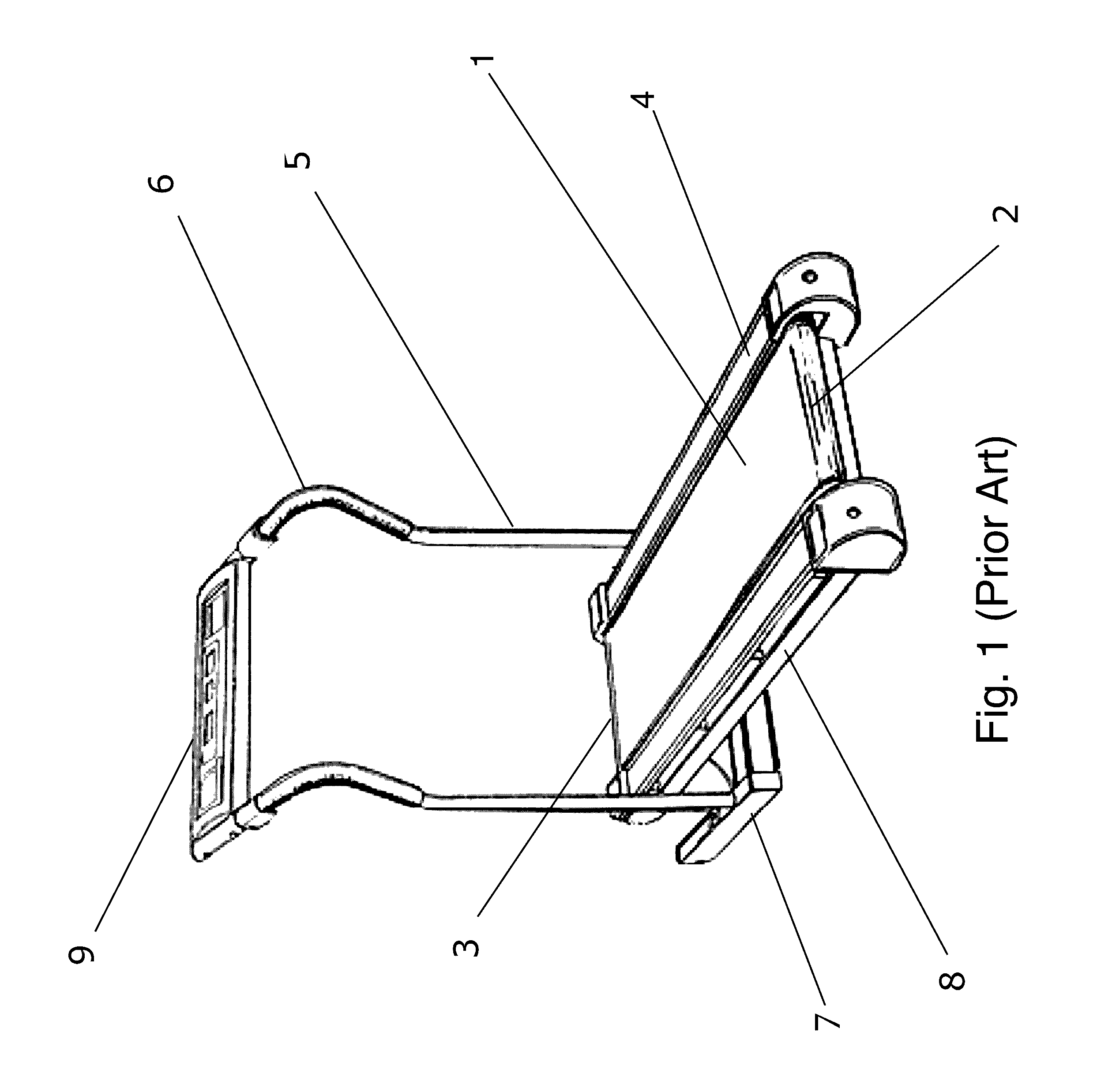
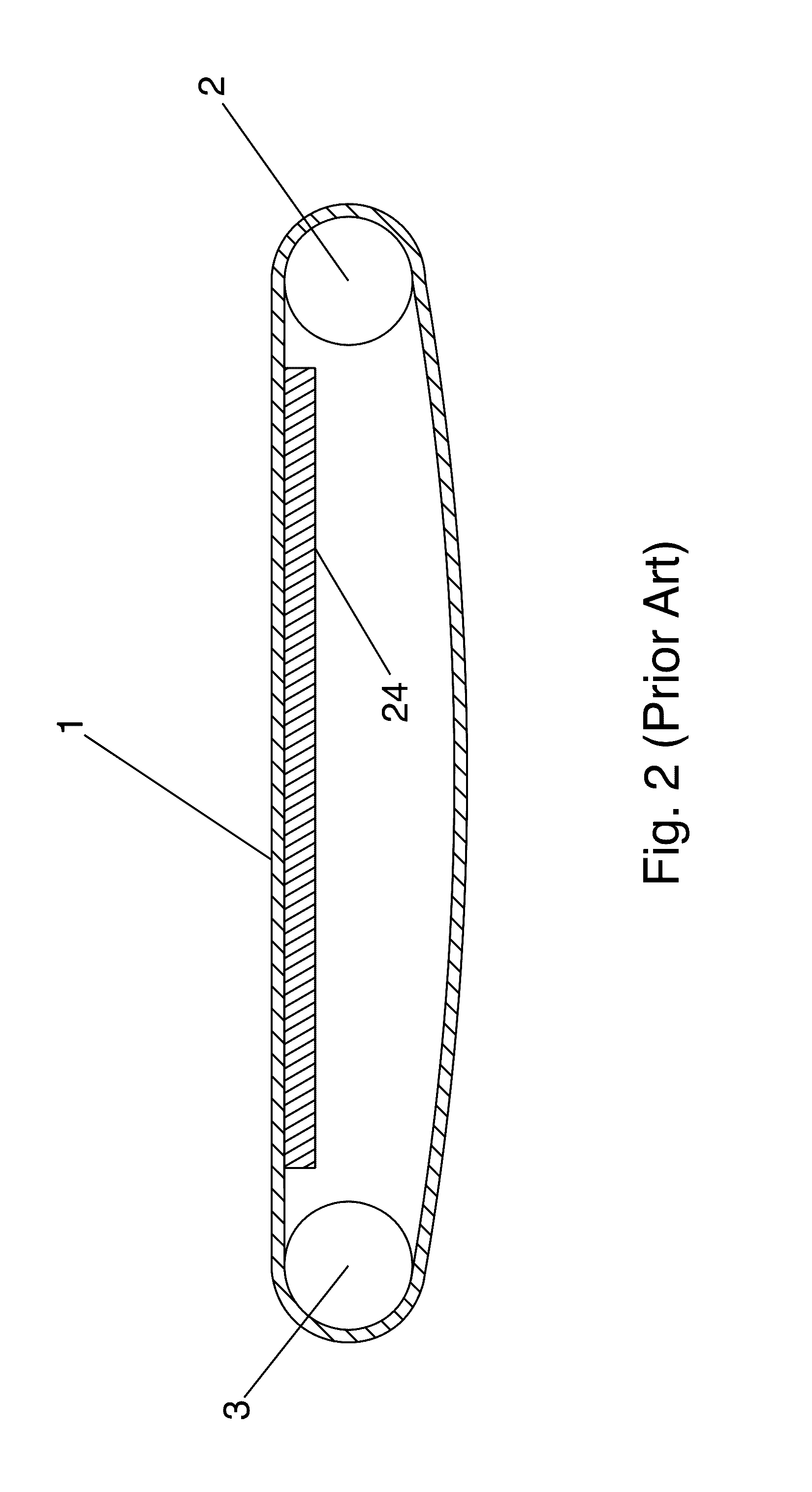
[0064]FIG. 1 shows a perspective view of a typical prior art treadmill. The belt 1 is a rubber belt that the user walks on. The belt wraps around rear roller 2 and front roller 3. On both sides of the treadmill there are stepping boards 4 that the user can use to rest on without walking. The stepping boards are mounted on the side rails 8, which are rigid metal beams that define a strong frame, to which various components are mounted, such as rollers 2 and 3. Upright poles 5 provide to the user through the handlebars 6, and also carry t...


PUM


Abstract

A computerized treadmill is provided. The treadmill deck may be fully suspended by a plurality of air suspension elements, such as bellows. The bellows may be pressurized by a computer-controlled compressor feeding a central air reservoir to which each bellows is connected via air hose. The bellows may be dampened to control expansion. A double hinge connecting the deck with frame may control lateral movement and reduce lateral load on the bellows. Incline and decline mechanisms facilitate a variety of deck angles. Control of the treadmill may be by computer, whether integrated or modular, whether traditional, laptop, tablet or smart phone. Control of the treadmill and conveyance of information associated with treadmill operation may be integrated with computer or smart phone applications, whether dedicated or third party.

Description

FIELD OF THE INVENTION[0001]The present invention relates in general to the exercise equipment field, and in particular, to treadmills having improvements in one or more areas such as deck support, deck positioning, console positioning and electronic controls.BACKGROUND OF THE INVENTION[0002]Modern society has created a lifestyle for many members of society that can be characterized as sedentary, with many hours of minimal or no physical activity, typically sitting at a desk or computer. Simultaneously, the diet of many people has deteriorated, with ensuing obesity, diabetes, heart disease and many other modern diseases. This lifestyle has also led to high growth in the cost of health care for society.[0003]Many of the above issues can be addressed through exercise. The treadmill is one of the most popular exercise machines available, and could play a major role in addressing issues of health and fitness. The treadmill typically provides a continuous rotating surface on which indivi...

Claims


Application Information

Patent Timeline
Patent Type & Authority Applications(United States)
IPC IPC(8): A63B22/02
CPCA63B2022/0214A63B22/02A63B21/0058A63B21/0083A63B21/0087A63B21/0088A63B22/0023A63B22/0207A63B22/0221A63B22/0228A63B22/0235A63B24/0087A63B71/0622A63B2024/0093A63B2071/0063A63B2071/065A63B2071/0683A63B2220/18A63B2220/30A63B2220/56A63B2220/833A63B2225/20A63B2225/50A63B2230/01
Inventor MOSER, GEORGE
Owner MOSER GEORGE
Learn More