
Shock absorber

a technology of shock absorber and shock absorber, which is applied in the direction of shock absorber, cycle equipment, transportation and packaging, etc., can solve the problems of easy contamination of air, easy contamination of control characteristics, and easy contamination, so as to suppress the occurrence of air entrainment and less easily affected by contaminants

Active Publication Date: 2016-10-06
HITACHI ASTEMO LTD
View PDF8 Cites 4 Cited by
  • Summary
  • Abstract
  • Description
  • Claims
  • Application Information

AI Technical Summary

Benefits of technology

The present invention provides a shock absorber that is less affected by contaminants and can prevent air from entering. This helps to improve the performance of the shock absorber and ensure it runs smoothly without experiencing any issues.

Problems solved by technology

Therefore, in the shock absorber having the configuration explained above, in some case, the contaminants intrude into the plunger that obtains the trust with the magnetic field generated in the solenoid, friction occurs, and a control characteristic is adversely affected.
The problem due to the contaminants easily occurs.
Even in such a configuration, the bearing section still cannot be a complete seal.
The contaminants are easily stuck.
Therefore, in particular, when contaminants of a magnetic material such as iron once occur, it is likely that the contaminants are held up and stuck.
Consequently, during the rise of the pressure, harmful effects occur, for example, the actuator cannot withstand the pressure and performs unintended movement.

Method used


Image

  • Shock absorber
  • Shock absorber
  • Shock absorber

Examples


Embodiment Construction

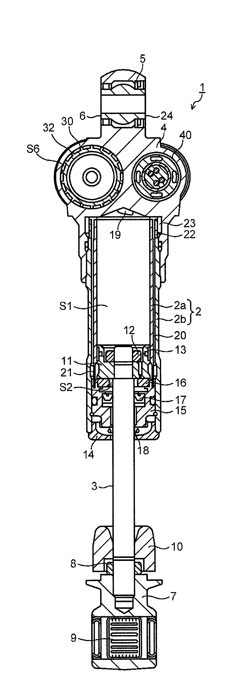
[0020]An embodiment of the present invention is explained below with reference to the drawings.

[0021][Structure of a Shock Absorber]

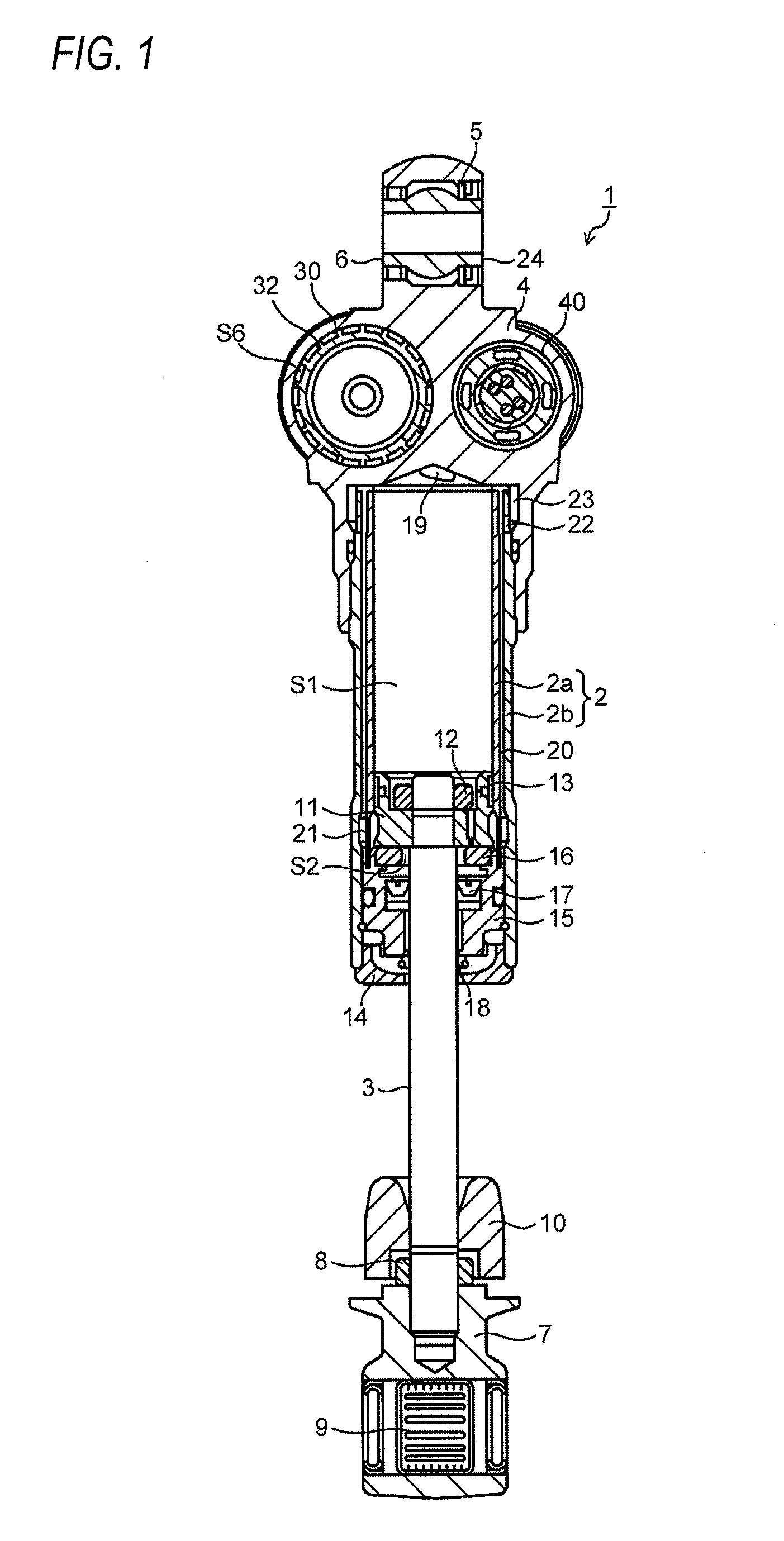
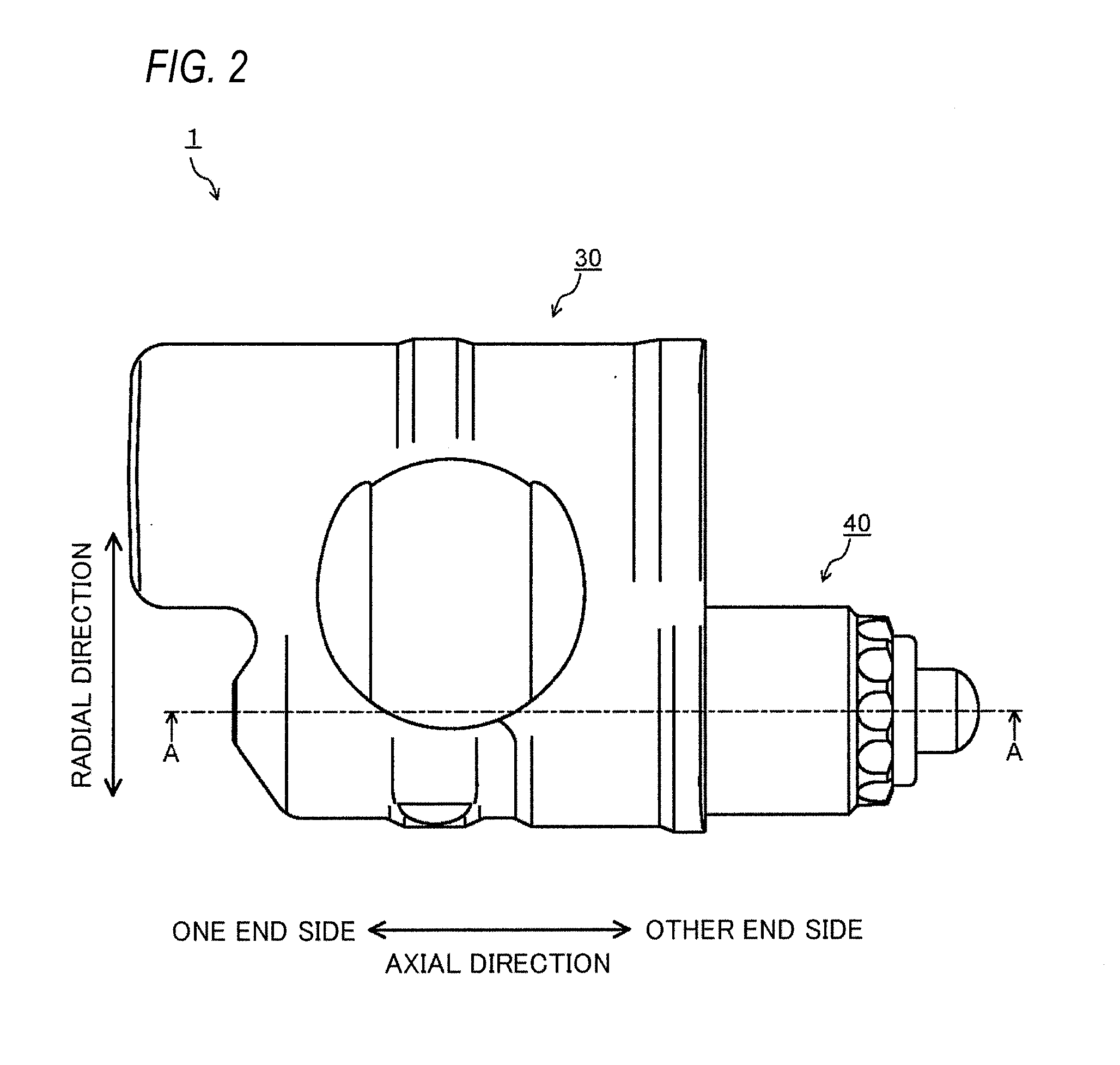
[0022]FIG. 1 is a longitudinal sectional view of a shock absorber 1 in the embodiment. FIG. 2 is a top view of a damping-force generating device shown in FIG. 1. FIG. 3 is an enlarged view of a main part of an A-A line cross section of FIG. 2. FIG. 4 is a main part enlarged detailed view of FIG. 3.

[0023]The shock absorber 1 in the embodiment is a rear cushion of an inverted type that suspend a rear wheel of a motorcycle on a vehicle body. In the shock absorber 1, as shown in FIG. 1, a part of a piston rod 3 attached to an axle side is inserted upward into the inside of a cylinder 2 attached to a vehicle body side. A suspension spring (not-shown) is interposed between the cylinder 2 and the piston rod 3.

[0024]The cylinder 2 is configured by an inner cylinder 2a and an outer cylinder 2b that form a concentric double tube. A damper case section 4 is attach...


PUM


Abstract

A shock absorber includes: a cylinder; a piston; a piston rod; and a damping-force generating device that controls a flow of oil, caused by sliding of the piston in the cylinder, wherein the damping-force generating device includes: a valve body that generates a damping force according to opening and closing of the valve body on a channel in which the oil flows; a valve seat on which the valve body seats to close the channel; and an actuator that includes a plunger generating thrust to the valve body in a valve closing direction and a plunger chamber in which the oil is filled in order to actuate the plunger, and the plunger chamber communicates with a downstream side in a flowing direction of the oil with reference to a place where the valve body seats on the valve seat.

Description

CROSS-REFERENCE TO RELATED APPLICATIONS[0001]This application is based on and claims priority under 35 USC 119 from Japanese Patent Application No. 2015-074208 filed on Mar. 31, 2015, the entire content of which is incorporated herein by reference.BACKGROUND[0002]1. Technical Field[0003]An embodiment of the present invention relates to a shock absorber including a damping-force generating device that controls a flow of oil occurring due to sliding of a piston in a cylinder and generates a damping force.[0004]2. Related Art[0005]For example, as a shock absorber used as a rear cushion that suspends a rear wheel of a motorcycle on a vehicle body, there is proposed a shock absorber including a cylinder in which the oil is filled, a piston slidably fit in the cylinder, and a piston rod coupled to the piston and extended to an outside of the cylinder. The shock absorber controls a flow of the oil due to the sliding of the piston in the cylinder and adjusts a damping force. As a shock abso...

Claims


Application Information

Patent Timeline
Patent Type & Authority Applications(United States)
IPC IPC(8): B62K25/28F16F9/44F16F9/34F16F9/19F16F9/18
CPCF16F9/19B62K25/283F16F9/44F16F9/34F16F9/185F16F9/465F16F2230/24
Inventor MURAKAMI, YOSUKE
Owner HITACHI ASTEMO LTD
Learn More