
Propeller-motor assembly for efficient thermal dissipation

a technology of motor assembly and motor, which is applied in the direction of mechanical energy handling, transportation and packaging, and efficient propulsion technologies, etc., can solve the problems of increasing the speed of motor no-load, affecting the performance and operation of generating heat for most electronic and electrical systems and devices. , to achieve the effect of increasing the rate of convective heat transfer

Active Publication Date: 2016-10-06
VANTAGE ROBOTICS LLC
View PDF16 Cites 19 Cited by
  • Summary
  • Abstract
  • Description
  • Claims
  • Application Information

AI Technical Summary

Benefits of technology

This patent describes a propeller drive assembly that includes a gap-filling thermally conductive material between the rotor and hub, as well as inwardly-extending radial vanes on the propeller that improve convective heat transfer. Additionally, a thermal interface material can be used to connect the hub and rotor, which can be a grease or a layer of flexible material. The propeller hub can also include internal vanes to increase heat transfer. These features enhance the efficiency of the propeller assembly and lead to improved performance.

Problems solved by technology

The performance and operation of most electronic and electrical systems and devices are adversely affected by heat.
Unfortunately, most electronic and electrical systems and devices generate heat as they operate.
Changes in these two key components of the motor will result in an increase in motor no-load speed and a decrease in motor locked rotor torque, altering the overall slope of the motor curve.
As the material temperature increases, atomic vibrations cause once-aligned magnetic moments to “randomize” resulting in a decrease in magnetic flux density.
If the maximum temperature rating of the magnets is exceeded, however, partial demagnetization will occur and permanently alter the performance of the motor.
Motor winding resistance is the main cause of heat generation within the motor.
Copper is an excellent conductor, however, it is not perfect.
Another potential cooling-related failure mode is that motors are commonly designed to include small air gaps between motor components, such as between the stator and the rotor, for maximum motor efficiency.
Modern electric motors used in AUVs often have air gaps that are similar in size to a grain of sand, making them vulnerable to having sand or other small particles caught in the air gap, causing the motor to seize.

Method used


Image

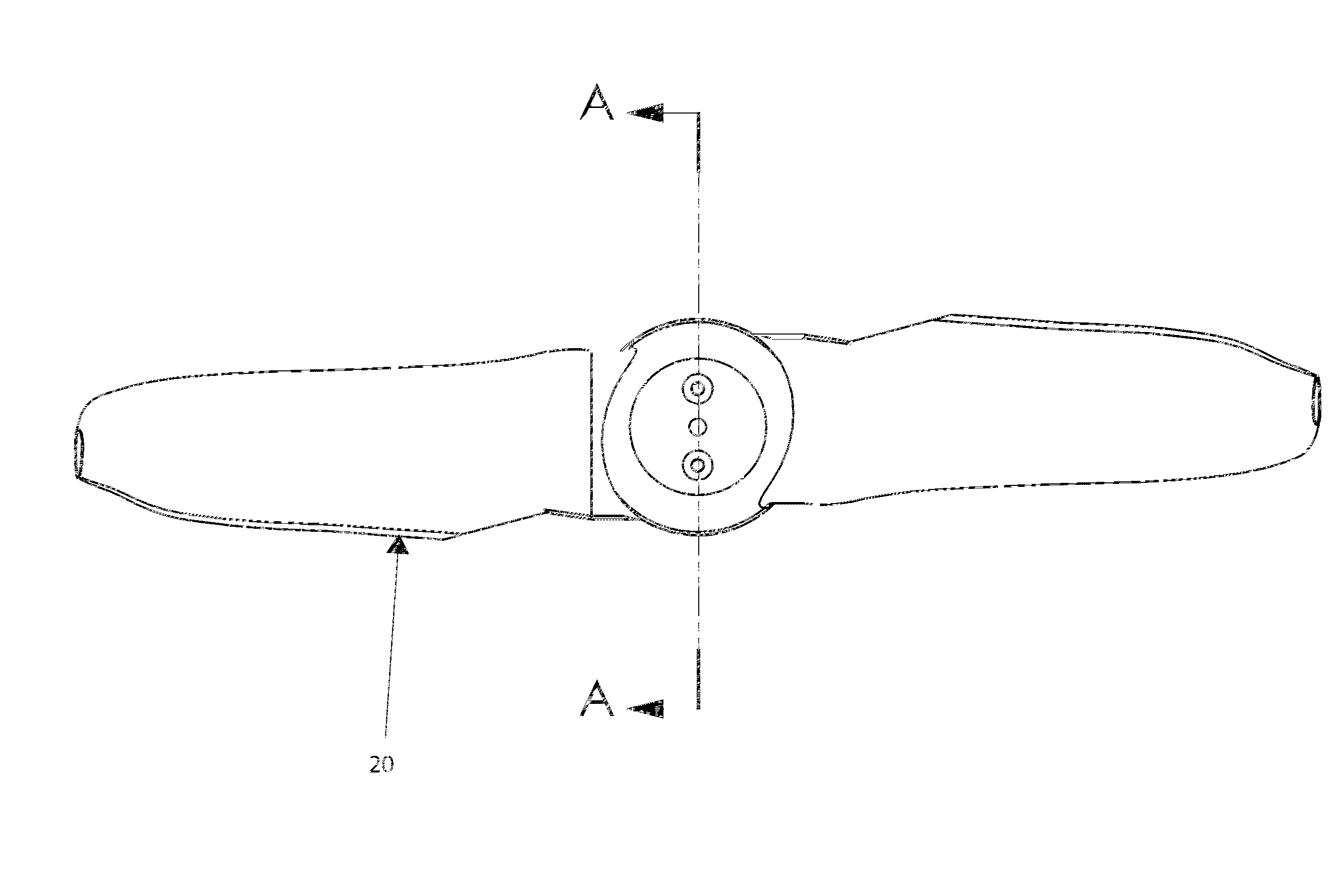
  • Propeller-motor assembly for efficient thermal dissipation
  • Propeller-motor assembly for efficient thermal dissipation
  • Propeller-motor assembly for efficient thermal dissipation

Examples


Embodiment Construction

[0030]Embodiments described herein relate to the management of thermal energy generated in electric motors during their operation. In certain embodiments, the thermal management can be used in conjunction with motors powering propellers, such as those used in quadcopters and other UAVs.

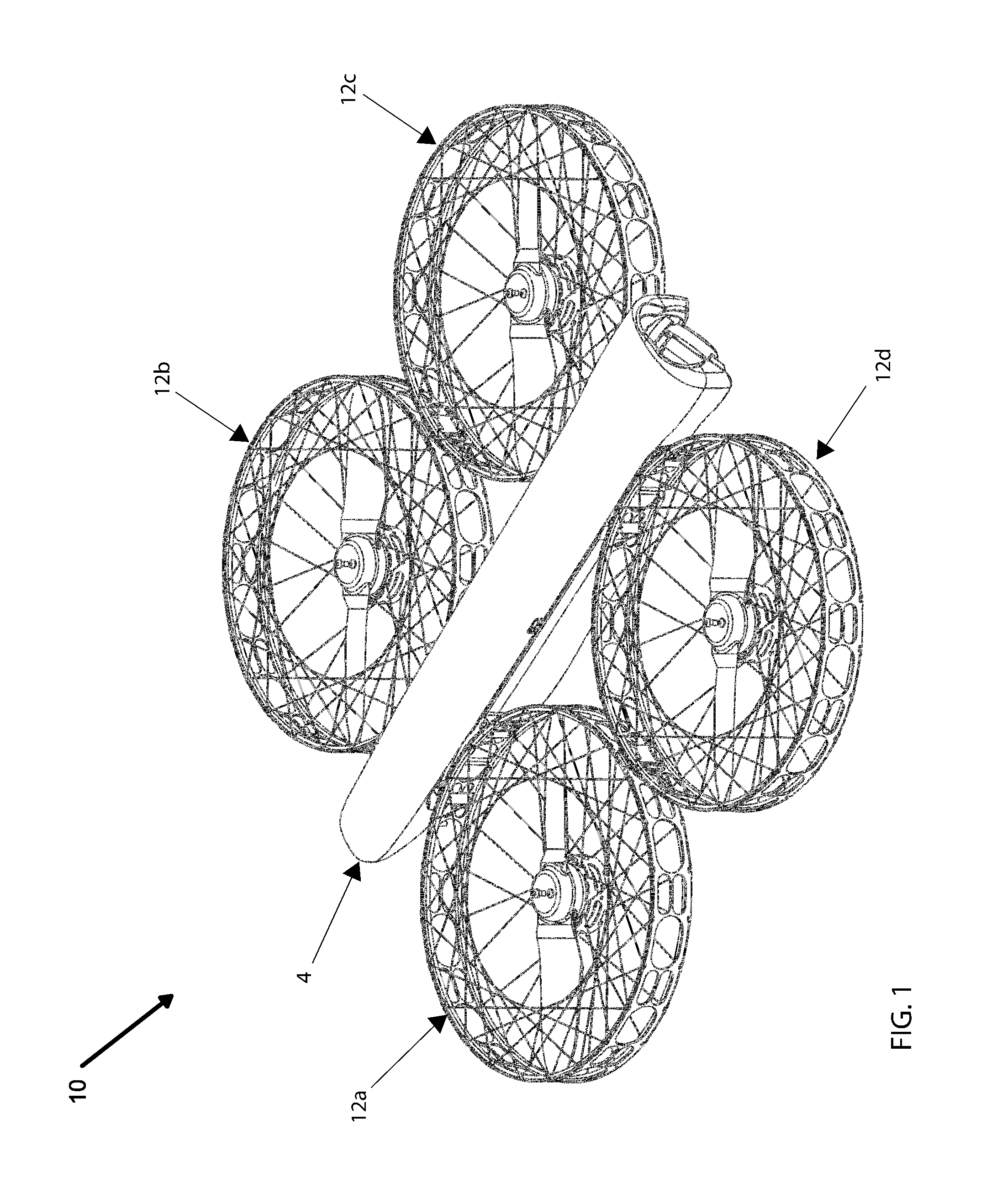
[0031]FIG. 1 is a perspective view of an exemplary unmanned aerial vehicle. The exemplary unmanned aerial vehicle (hereafter “UAV”) is, in the illustrated embodiment, a quadcopter 10. UAV quadcopter 10 includes four thrust pods 12a-d secured relative to a body 4, with each thrust pod including a propeller drive assembly including a motor and a propeller. In other embodiments, however, UAVs having additional or fewer propellers can be used. Additional details of UAVs such as quadcopter 10 are described in U.S. application Ser. No. 14 / 990,057, filed Jan. 7, 2016 and entitled “UNMANNED AERIAL VEHICLE WITH PROPELLER PROTECTION AND HIGH IMPACT-SURVIVABILITY,” the disclosure of which is hereby incorporated ...


PUM


Abstract

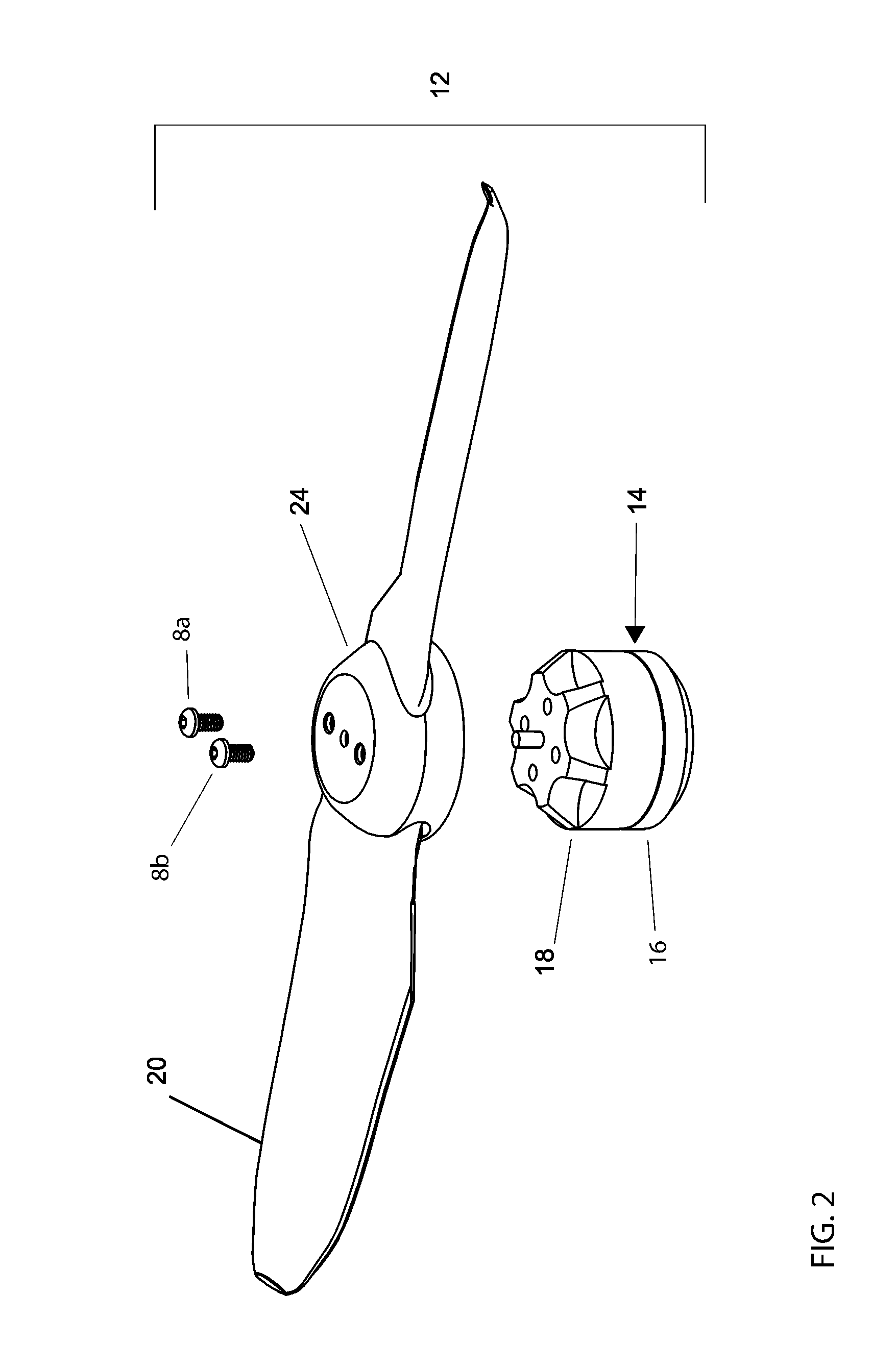
A propeller drive assembly includes an electric motor having a stator and a rotor. During operation the motor generates heat. A propeller made from a thermally conductive plastic includes a hub that is secured to the rotor portion of the motor so that the heat generated within the motor is transferred by conductance through the thermally conductive hub and propeller and then, by convection, is absorbed by the surrounding air, as the propeller rotates through the air. A thermally conductive interface material can be positioned between the rotor portion of the motor and the hub of the propeller to increase the thermal efficiency of the heat transfer between the motor and the propeller. A thermally conductive grease can be used as the interface material and an O-ring seal can be provided about the rotor to prevent the grease from escaping during motor operation.

Description

CROSS-REFERENCE TO RELATED APPLICATIONS[0001]This application claims the benefit of U.S. Provisional Application No. 62 / 141,143, filed Mar. 31, 2015, entitled “Propeller-Motor Assembly for Efficient Thermal Dissipation,” which is hereby incorporated by reference in its entirety.BACKGROUND[0002]1. Technical Field[0003]Embodiments disclosed herein generally relate to propeller driven unmanned aerial vehicles of the type that are powered by electric motors. Specifically, certain embodiments disclosed herein relate to methods and structures which can be used to manage heat dissipation from the electric motors in such vehicles.[0004]2. Description of the Related Art[0005]The performance and operation of most electronic and electrical systems and devices are adversely affected by heat. Unfortunately, most electronic and electrical systems and devices generate heat as they operate. The generated heat must be managed to prevent a reduction in performance or overall operational failure of su...

Claims


Application Information

Patent Timeline
Patent Type & Authority Applications(United States)
IPC IPC(8): B64C11/02B64C11/20B64D27/24B64C39/02B64D33/08
CPCB64C11/02B64C39/024B64D33/08B64C2201/108B64C11/20B64C2201/042B64C2201/024B64D27/24H02K5/02H02K7/14Y02T50/60H02K9/223H02K9/227B64U50/19B64U30/26B64U10/14
Inventor FISHER, TOBINVAN NIEKERK, JOHANNES BECKER
Owner VANTAGE ROBOTICS LLC
Learn More