Asymmetrically-Shaped Combustion Chamber For Opposed-Piston Engines

a technology of opposed pistons and combustion chambers, applied in the direction of reciprocating piston engines, positive displacement engines, combustion engines, etc., can solve the problems of reducing combustion efficiency, reducing air utilization and thus thermal efficiency, partial flame quenching and production of soot, etc., to reduce emissions, reduce the durability of pistons, and reduce the disadvantages of fuel efficiency

Active Publication Date: 2016-10-06
ACHATES POWERS INC
View PDF4 Cites 14 Cited by
  • Summary
  • Abstract
  • Description
  • Claims
  • Application Information

AI Technical Summary

Benefits of technology

[0006]The disadvantages with respect to fuel efficiency, emissions reduction, and piston durability are reduced if not eliminated by providing a combustion chamber for an opposed-piston engine having a shape to accommodate both fuel plume spreading and fuel plume movement in response to swirl. In this regard, the combustion chamber has an elongated asymmetrical shape in longitudinal section that runs along a chamber centerline, between diametrically-opposed openings of the combustion chamber through which fuel is injected. The asymmetry apportions combustion chamber so as to provide additional clearance on a side of the chamber centerline toward which swirl is directed, thereby giving a fuel plume space to adequately entrain air in the presence of swirl.

Problems solved by technology

Combustion chamber symmetry may in some instances reduce combustion efficiency.
The swirl component of charge air tends to urge the plumes of fuel toward respective ridges that define the sides of the combustion chamber, thereby reducing air utilization and hence thermal efficiency.
Combustion chamber symmetry may also work against effective control of emissions if swirl pushes the plumes into contact with the sides of the combustion chamber, which can cause partial flame quenching and production of soot.
Another possible drawback of symmetry can occur if the plumes ignite while in contact with the sides, which can result in increased heat transfer to the piston crown and risk of crown oxidation.

Method used


Image

  • Asymmetrically-Shaped Combustion Chamber For Opposed-Piston Engines
  • Asymmetrically-Shaped Combustion Chamber For Opposed-Piston Engines
  • Asymmetrically-Shaped Combustion Chamber For Opposed-Piston Engines

Examples


Embodiment Construction

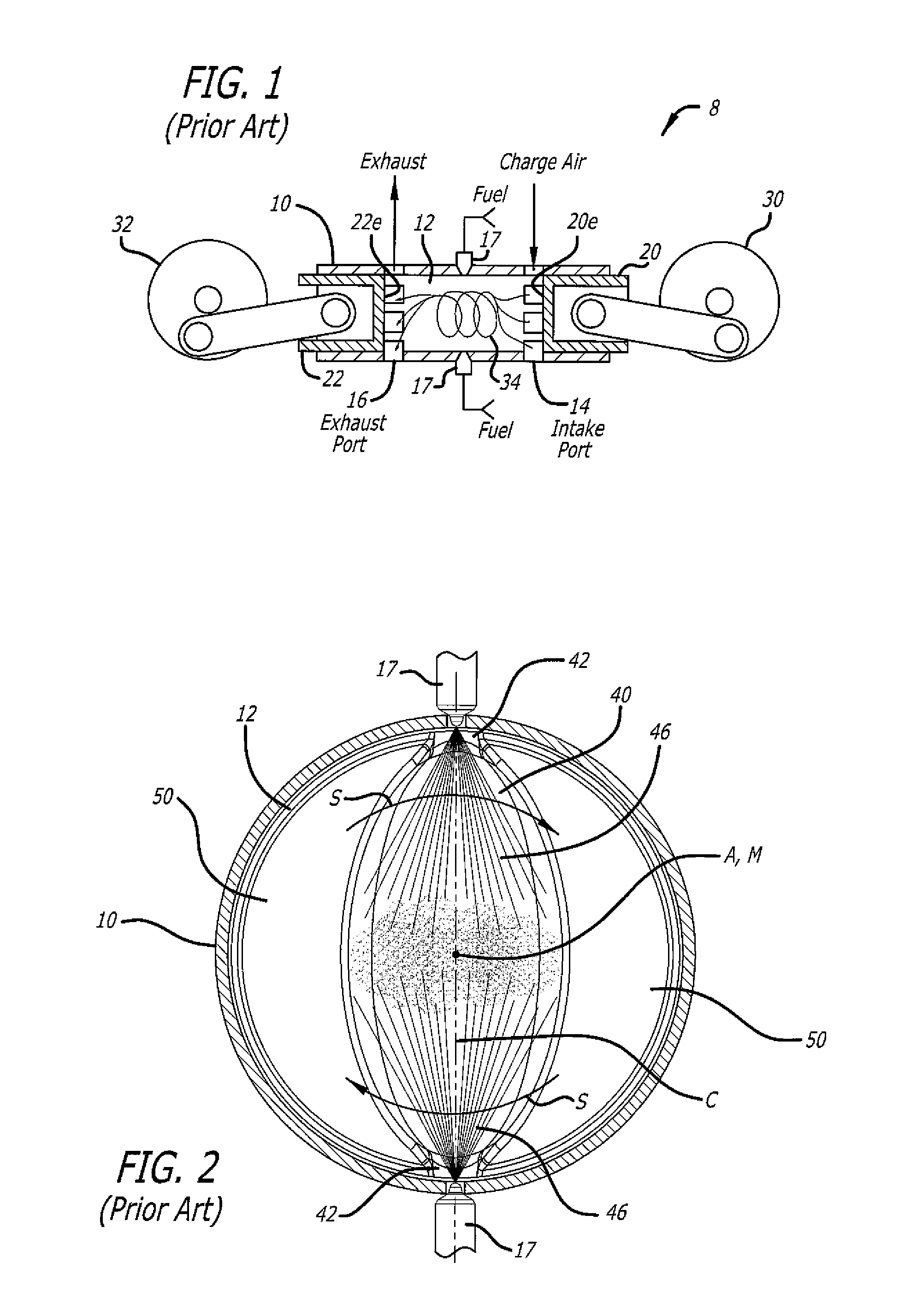
[0023]Per FIG. 1 an opposed-piston, two-stroke engine 8 includes at least one cylinder 10 with a bore 12 and longitudinally displaced intake and exhaust ports 14 and 16 machined or formed in the cylinder, near respective ends thereof. Each of the intake and exhaust ports includes one or more circumferential arrays of openings in which adjacent openings are separated by a solid portion of the cylinder wall (also called a “bridge”). In some descriptions, each opening is referred to as a “port”; however, the construction of a circumferential array of such “ports” is no different than the port constructions in FIG. 1.

[0024]Fuel injection nozzles 17 are secured in threaded holes that open through the side surface of the cylinder. Two pistons 20, 22 are disposed in the bore 12 with their end surfaces 20e, 22e in opposition to each other. For convenience, the piston 20 is referred to as the “intake” piston because of its proximity to the intake port 14. Similarly, the piston 22 is referred...


PUM


Abstract

A combustion chamber for an opposed-piston engine has an elongated asymmetrical shape in longitudinal section that runs along a chamber centerline, between diametrically-opposed openings of the combustion chamber through which fuel is injected. The asymmetry apportions combustion chamber volume to provide additional clearance on a side of the chamber centerline toward which swirl is directed, thereby giving a fuel plume space to swing without hindrance in response to swirl.

Description

RELATED APPLICATIONS[0001]This application contains subject matter related to the subject matter of the following commonly-owned applications: U.S. Ser. No. 13 / 066,589, now U.S. Pat. No. 8,800,528; U.S. Ser. No. 13 / 136,954, now U.S. Pat. No. 8,820,294; U.S. Ser. No. 14 / 117,831, published as US 2014 / 0083396; U.S. Ser. No. 13 / 843,686, published as US 2013 / 0213342; U.S. Ser. No. 14 / 026,931, published as US 2014 / 0014063; and U.S. Ser. No. 14 / 074,580.FIELD OF THE DISCLOSURE[0002]The field includes opposed-piston engines in which a combustion chamber is defined between end surfaces of pistons disposed in opposition in the bore of a cylinder. More particularly, the field includes opposed-piston engines with combustion chambers having shapes that promote complex, turbulent bulk motion of charge air.BACKGROUND OF THE DISCLOSURE[0003]The related patent applications describe two-stroke, opposed-piston engines in which pairs of pistons move in opposition in the bores of ported cylinders. During...

Claims


Application Information

Patent Timeline
Patent Type & Authority Applications(United States)
IPC IPC(8): F02B75/02F02F3/00
CPCF02B75/02F02B2075/025F02F3/00F02B23/0618F02B23/0621F02B23/0624F02B23/0633F02B23/066F02B23/0669F02B23/0678F02B23/069F01B7/14F02B75/282Y02T10/12
Inventor ABANI, NEERAVMACKENZIE, RYAN G.VENUGOPAL, RISHIKESH
Owner ACHATES POWERS INC
Why Eureka
Try Eureka