Electric water pump

Inactive Publication Date: 2016-10-06
HYUNDAI MOTOR CO LTD
View PDF9 Cites 4 Cited by
  • Summary
  • Abstract
  • Description
  • Claims
  • Application Information

AI Technical Summary

Benefits of technology

The present patent aims to improve the cooling performance of an electric water pump by adding a wing portion to increase the flow of coolant. This will lead to better cooling performance.

Problems solved by technology

Therefore, the heater and the radiator do not properly operate where the engine speed is slow.
However, if the engine speed is increased, the fuel consumption of a vehicle is also increased.
Because of such a space constraint, the amount of coolant that flows between the stator and the rotor is not sufficient, and the coolant flow is not smooth.
Therefore, the heat produced in the electric water pump is difficult to remove therefrom.

Method used


Image

  • Electric water pump
  • Electric water pump
  • Electric water pump

Examples


Embodiment Construction

[0015]An exemplary embodiment of the present disclosure will hereinafter be described in detail with reference to the accompanying drawings.

[0016]Throughout this specification and the claims which follow, In addition, unless explicitly described to the contrary, the word “comprise” and variations such as “comprises” or “comprising” will be understood to imply the inclusion of stated elements but not the exclusion of any other elements.

[0017]For better comprehension and ease of description, a direction which is left side of a drawing is referred to as “a front surface”, “a front portion”, or “frontward”, and the opposite direction is referred to as “a rear side”, “a rear portion” or “rearward”.

[0018]Throughout the specification, components denoted by the same reference numerals are the same or similar components.

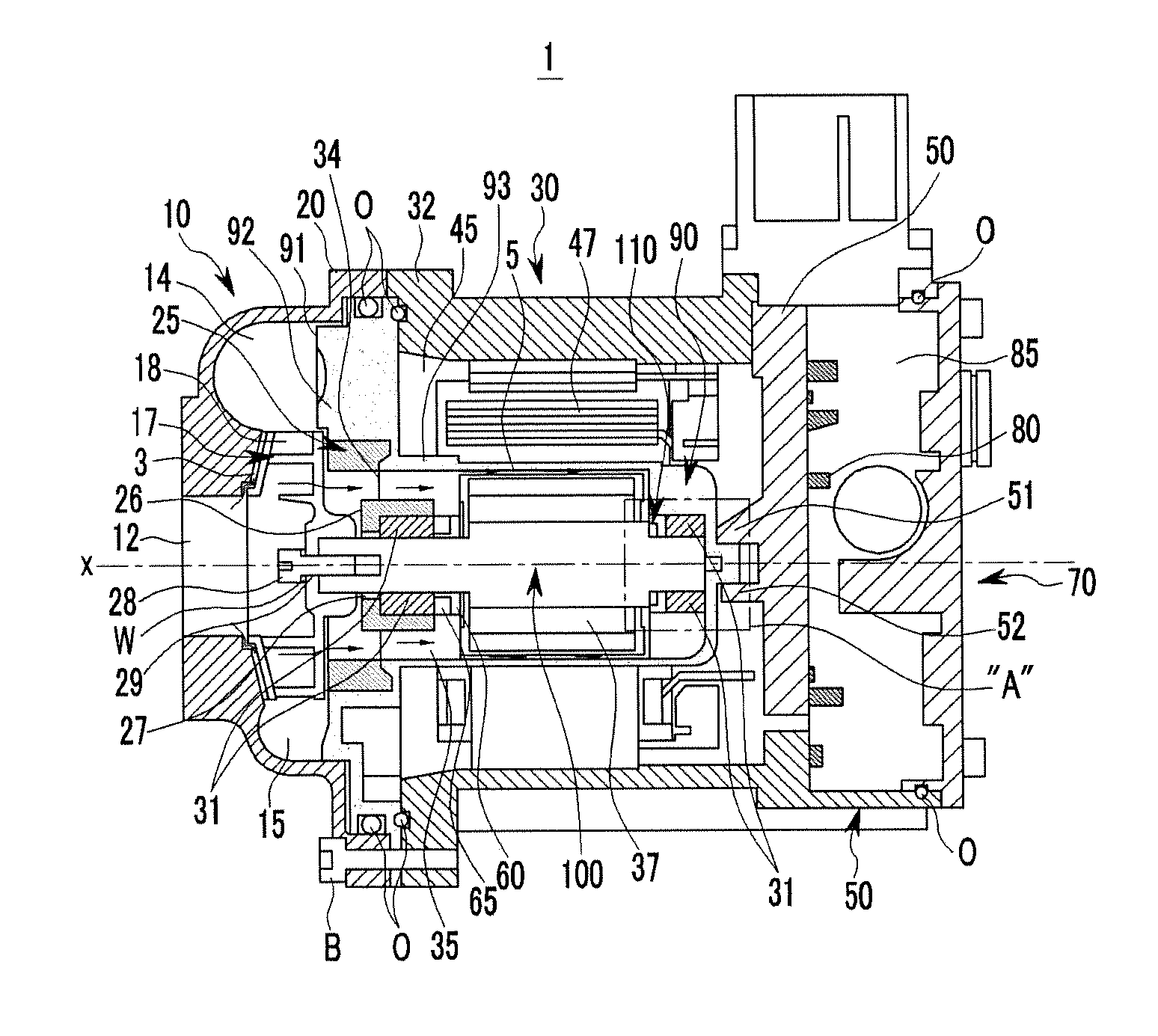
[0019]FIG. 1 is a cross-sectional view of an electric water pump according to an exemplary embodiment of the present disclosure.

[0020]An electric water pump 1 according to an...


PUM


Abstract

An electric water pump includes a pump cover having an inlet through which coolant flows; a stator chamber having a stator generating a magnetic field according to a control signal; a rotor chamber having a rotor rotating according to the magnetic field generated by the stator; a separation wall configured to separate the stator chamber from the rotor chamber; a shaft having a central axis, fixed to the rotor so as to rotate together with the rotor about the central axis thereof; and an impeller fixed to a front portion of the shaft so as to rotate together with the shaft, the impeller pressurizing a coolant having flowed in through the inlet, wherein at least one wing portion is formed on a part of the shaft to increase a flow of the coolant.

Description

CROSS-REFERENCE TO RELATED APPLICATION[0001]This application claims the benefit of priority to Korean Patent Application No. 10-2015-0046992, filed in the Korean Intellectual Property Office on Apr. 2, 2015, the entire contents of which are incorporated herein by reference.TECHNICAL FIELD[0002]The present disclosure relates to an electric water pump. More particularly, the present disclosure relates an electric water pump having a wing portion in order to increase a flow of a coolant.BACKGROUND[0003]Generally, a water pump circulates coolant to an engine and a heater to cool the engine and heat a cabin. The coolant flowing out from the water pump circulates through and exchanges heat with the engine, the heater and / or the radiator, and flows back in the water pump.[0004]The water pump is connected to a pulley fixed to a crankshaft of the engine and is driven according to the rotation of the crankshaft (i.e., the rotation of the engine). Therefore, the coolant amount flowing from the...

Claims


Application Information

Patent Timeline
IPC IPC(8): F04D29/58
CPCF04D29/5806F04D29/043F04D29/2272F04D29/586F01P2005/046F04D13/0606F01P5/10
Inventor LEE, BONG SANG
Owner HYUNDAI MOTOR CO LTD
Why Eureka
Try Eureka