
Vehicle differential device

a technology of differential device and vehicle, which is applied in the direction of gearing details, mechanical equipment, gearing, etc., to achieve the effect of simple structure and efficient removal of lubricant oil

Inactive Publication Date: 2016-10-06
MUSA PRECISION IND CO LTD
View PDF1 Cites 3 Cited by
  • Summary
  • Abstract
  • Description
  • Claims
  • Application Information

AI Technical Summary

Benefits of technology

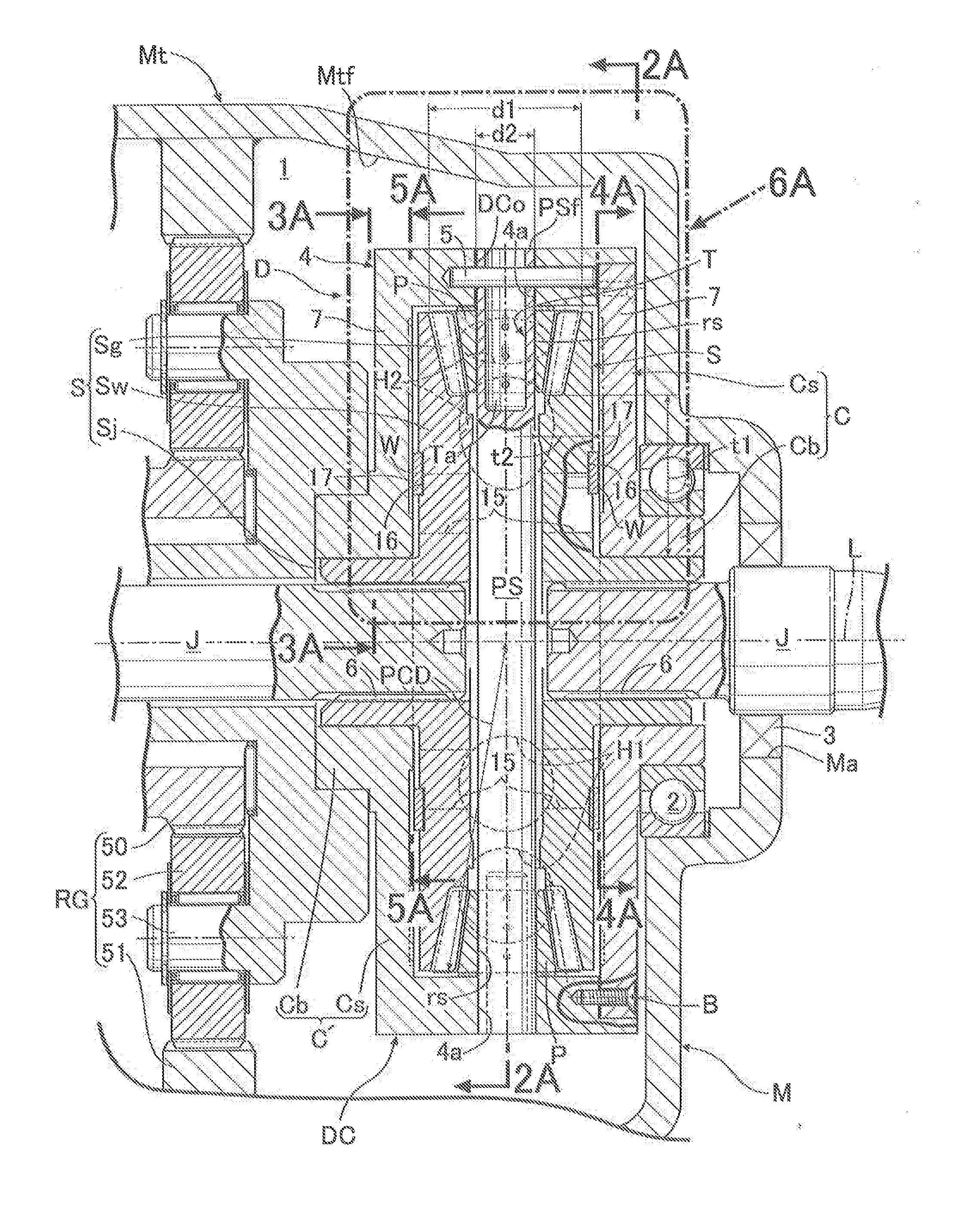
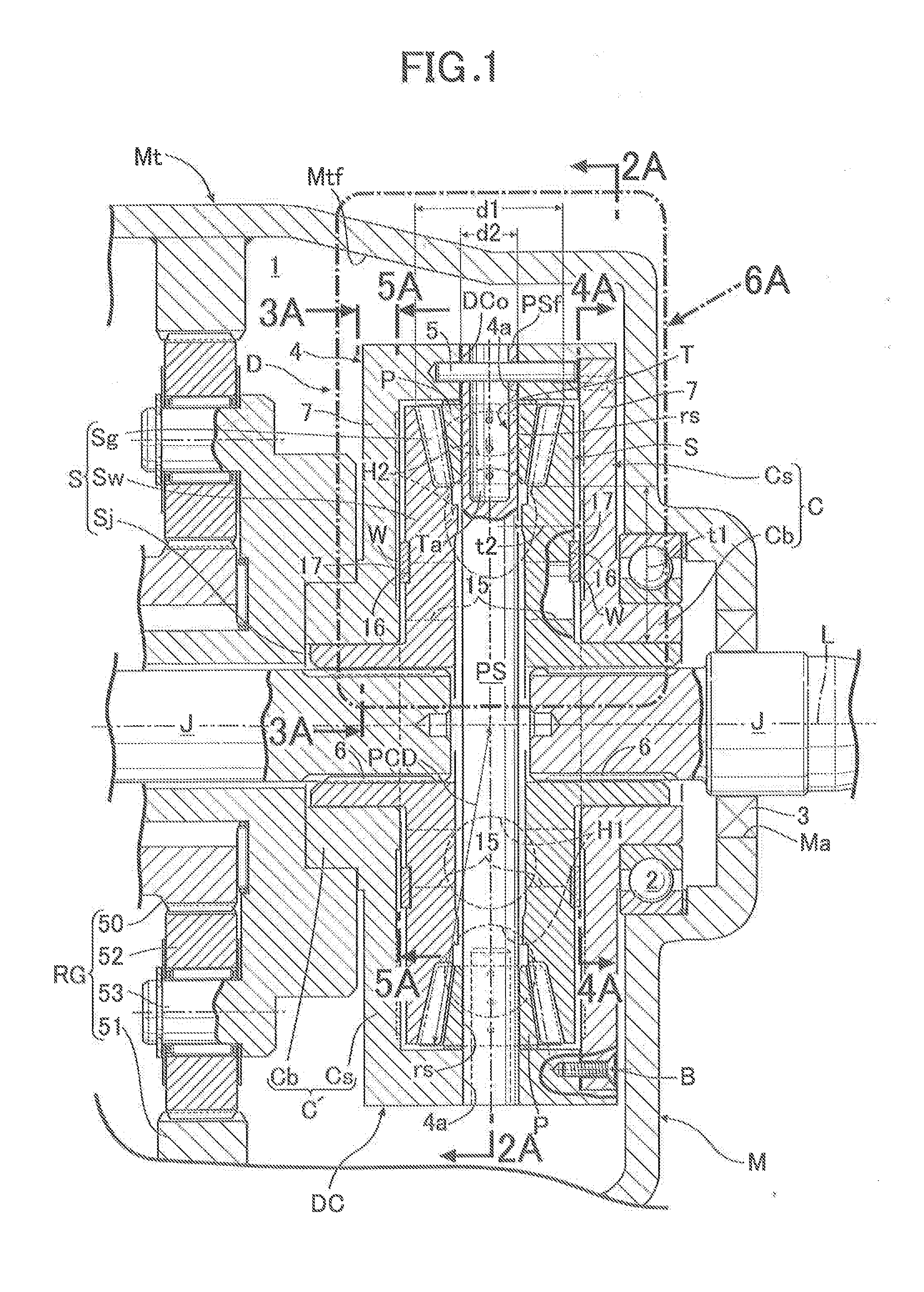
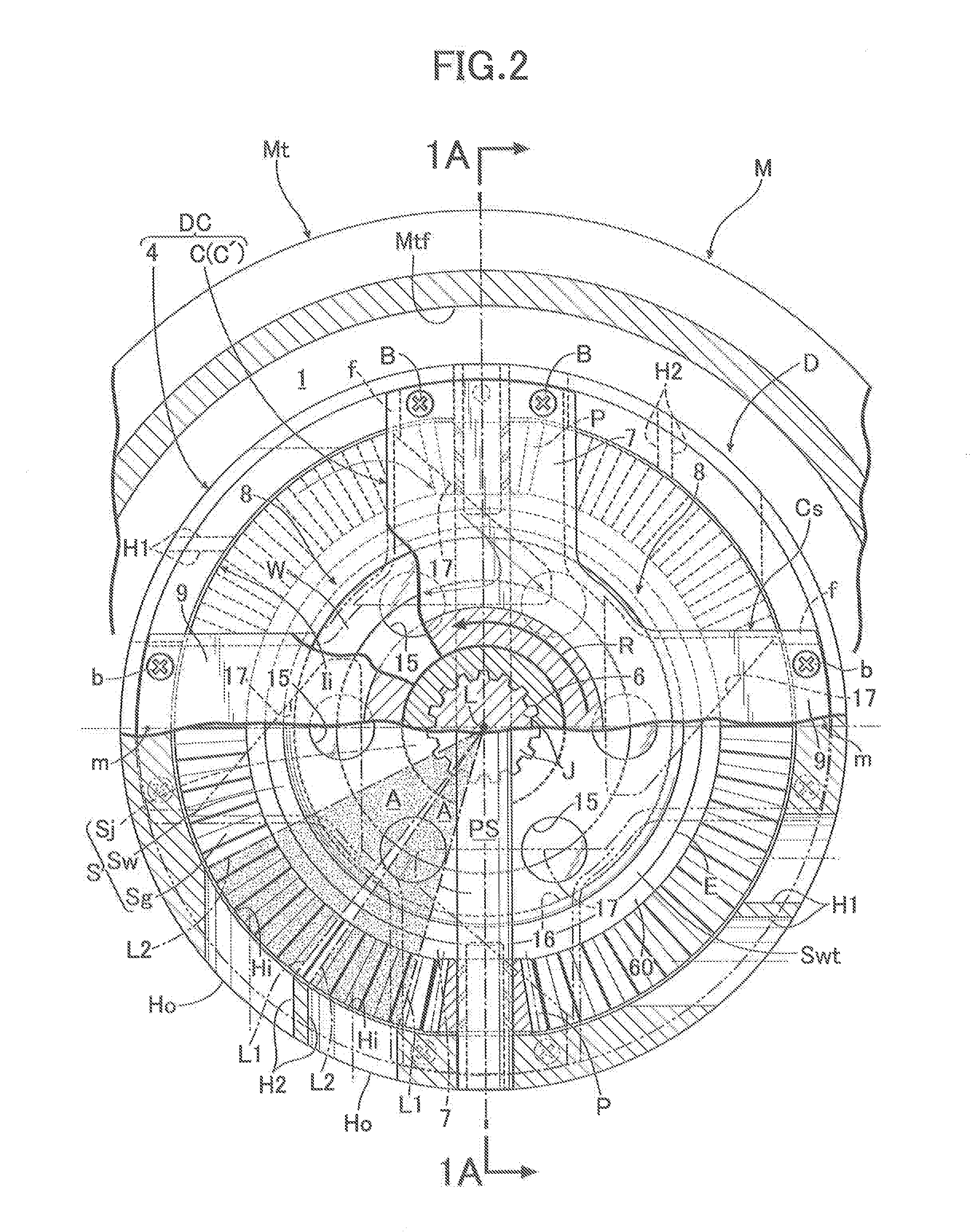
The present invention provides a vehicle differential device that can efficiently take lubricant oil from the transmission case into the differential case, particularly to the rotation sliding portions between the pinions and the pinion shaft. This is achieved by arranging multiple oil intake holes in the outer peripheral wall of the differential case, which are offset towards the pinions in the rotational direction of the differential case. The oil intake holes are formed so that the lubricant oil can flow towards the rotation sliding portions between the pinions and the pinion shaft. This efficient lubrication can enhance the overall lubricating effect of the differential device.

Problems solved by technology

Although, however, the differential device of Japanese Patent No. 3915719 is designed with consideration of positions and orientations of the plurality of oil intake holes provided to the outer peripheral wall of the differential case, the design is only intended to efficiently scrape up or scoop up the lubricant oil held in a bottom portion of a transmission case into the differential case.

Method used


Image

  • Vehicle differential device
  • Vehicle differential device
  • Vehicle differential device

Examples


Embodiment Construction

[0034]An embodiment of the present invention will be described below based on the attached drawings.

[0035]First of all, in FIG. 1, a differential device D is connected to an engine (not illustrated) as a power source mounted on an automobile via a speed reduction gear mechanism RG. The differential device D drives left and right axles while allowing differential rotation between the left and right axles by distributively transmitting to a pair of left and right output shafts J rotational force which is transmitted from the engine to a differential case DC via the speed reduction gear mechanism RG, the pair of left and right output shafts J being continuous respectively to the pair of left and right axles. The differential device D is housed together with the speed reduction gear mechanism RG in, for example, a transmission case M placed beside the engine in a front portion of a vehicle body, in a way that the differential device D is adjacent to the speed reduction gear mechanism RG...


PUM


Abstract

Differential case includes multiple oil intake holes being respectively at positions offset from intermediate point between two pinions adjacent peripherally in the case toward the pinions, the holes passing through outer peripheral wall of the case in inside-outside direction and being capable of taking lubricant oil into the case. The holes are formed such that as seen in projection plane orthogonal to rotation axis of the case, axes of the holes extending from inner to outer opening ends of the holes are inclined forward in rotational direction of the case when vehicle travels forward. As seen in the projection plane, the pinions are placed outside areas between first and second imaginary lines, the first imaginary lines joining the axis and one peripheral ends of the inner opening ends, the second imaginary lines joining the axis and the other peripheral ends thereof.

Description

BACKGROUND OF THE INVENTION[0001]1. Field of the Invention[0002]The present invention relates to a differential device, particularly a vehicle differential device which distributively transmits rotational force to a pair of output shafts, the rotational force being transmitted from a vehicle-installed power source to a differential case, the differential case being housed in a transmission case.[0003]2. Description of the Related Art[0004]Conventionally, as the above-mentioned kind of differential device, Japanese Patent No. 3915719, for example, has made known a differential device including a plurality of oil intake holes which are formed in an outer peripheral wall of the differential case at intervals in its peripheral direction so as to pass through the outer peripheral wall in an inside-outside direction and take lubricant oil into the differential case.[0005]Although, however, the differential device of Japanese Patent No. 3915719 is designed with consideration of positions a...

Claims


Application Information

Patent Timeline
Patent Type & Authority Applications(United States)
IPC IPC(8): F16H57/04F16H48/40F16H48/08
CPCF16H57/0483F16H48/40F16H57/043F16H48/08F16H2048/102
Inventor MORI, HIROYUKI
Owner MUSA PRECISION IND CO LTD
Learn More