System and method for calibration of echo sounding systems and improved seafloor imaging using such systems

a sounding system and calibration method technology, applied in the field of system and method for calibration improving seafloor imaging using such systems, can solve the problems of limiting the ability to achieve calibration, increasing the number of soundings, and limiting the patch test and quantitative error minimization approach of bjorke, so as to increase the resolvability of echo sounding systems, reduce acquisition speed, and increase the sounding density along the track

Active Publication Date: 2016-10-06
ORANGE DANIEL L
View PDF3 Cites 1 Cited by
  • Summary
  • Abstract
  • Description
  • Claims
  • Application Information

AI Technical Summary

Benefits of technology

[0015]In a further aspect of the invention, a method is provided for increasing the resolvability of an echo sounding system by acquiring multiple survey lines to produce overlapping swaths of seafloor data. Adjacent survey lines of the multiple survey lines may have a line offset that is less than a swath width. Alternatively, or in combination, the multiple survey lines may be acquired on multiple different headings to generate overlapping swaths of seafloor data. The method may further comprise acquiring the multiple survey lines at reduced acquisition speed to increase the sounding density along-track. The seafloor bathymetric data may be binned at progressively smaller bin sizes with progressively more overlap to further improve resolvability. The seafloor backscatter data may be mosaiced at progressively smaller pixel sizes with progressively more overlap to further improve resolvability.
[0016]Still anothe...

Problems solved by technology

Both the patch test and the quantitative error minimization approach of Bjorke are limited by the noise inherent to any acoustic surveying system.
This noise will limit the ability to achieve a calibration because the user reaches a point at wh...

Method used


Image

  • System and method for calibration of echo sounding systems and improved seafloor imaging using such systems
  • System and method for calibration of echo sounding systems and improved seafloor imaging using such systems
  • System and method for calibration of echo sounding systems and improved seafloor imaging using such systems

Examples


Embodiment Construction

[0030]For purposes of the present description, the following definitions will be used:

[0031]“Vehicle” means any ship, towfish, autonomous underwater vehicle (AUV), submarine, boat, barge, raft, etc. that can be used to acquire echo sounding data.

[0032]“Seafloor” means the ocean floor or the bottom of any body of water, natural or man-made (lake, river, stream, harbour, ocean, canal, marina, etc.)

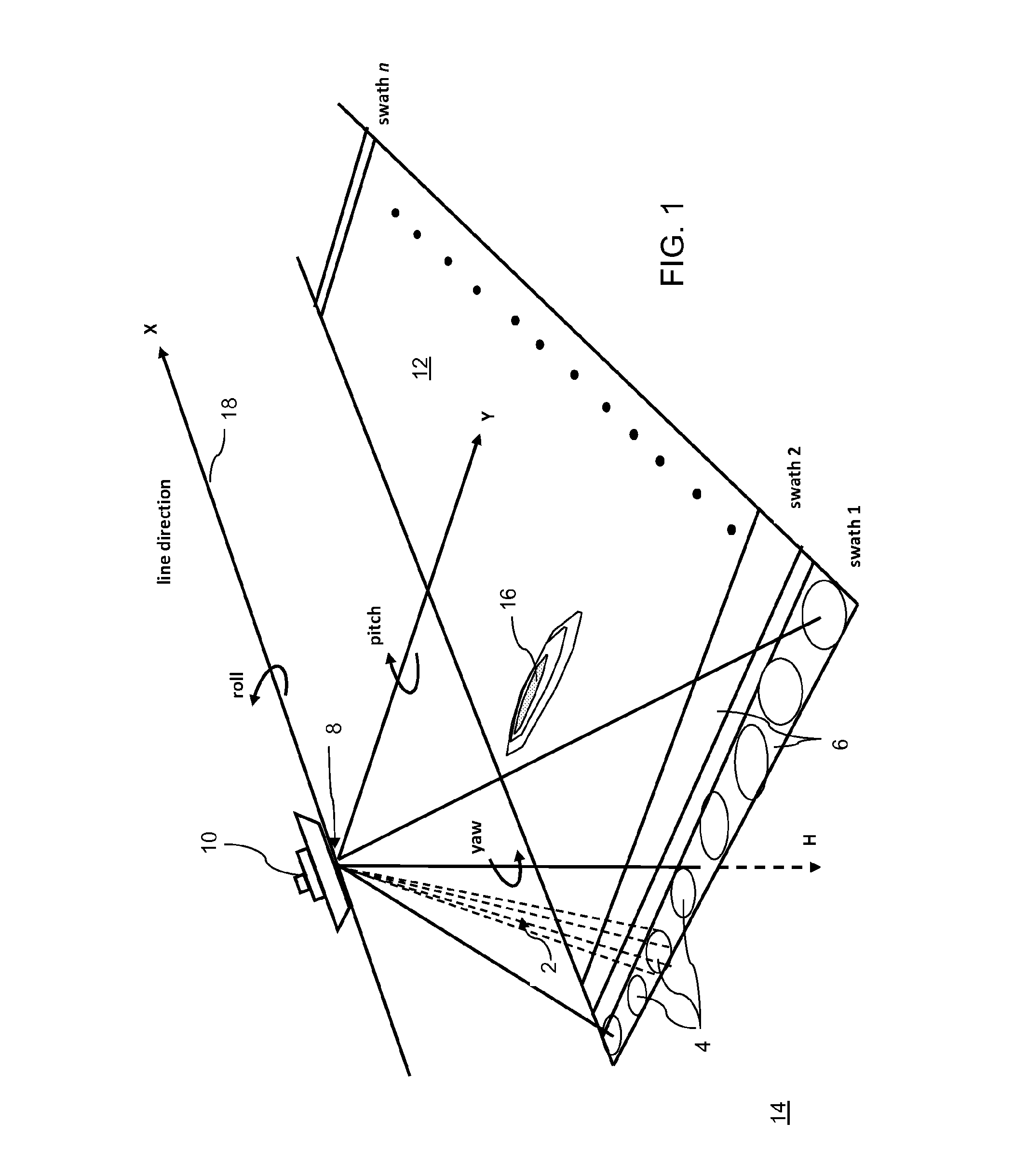
[0033]FIG. 1 illustrates the basic elements of an echo sounding measurement. A vehicle 10 moves along a direction X while making echo sounder measurements of the seafloor 14. In a multibeam technique, an acoustic array mounted parallel to the length of the ship transmits acoustic energy in a fan-shaped pattern 2, narrow along-track and broad across-track (swath 1). A second acoustic array, perpendicular to the first and mounted athwartship, receives acoustic signals from a fan-shaped area that is narrow across-track, and elongate along-track. The area of the seafloor in common between the tr...


PUM


Abstract

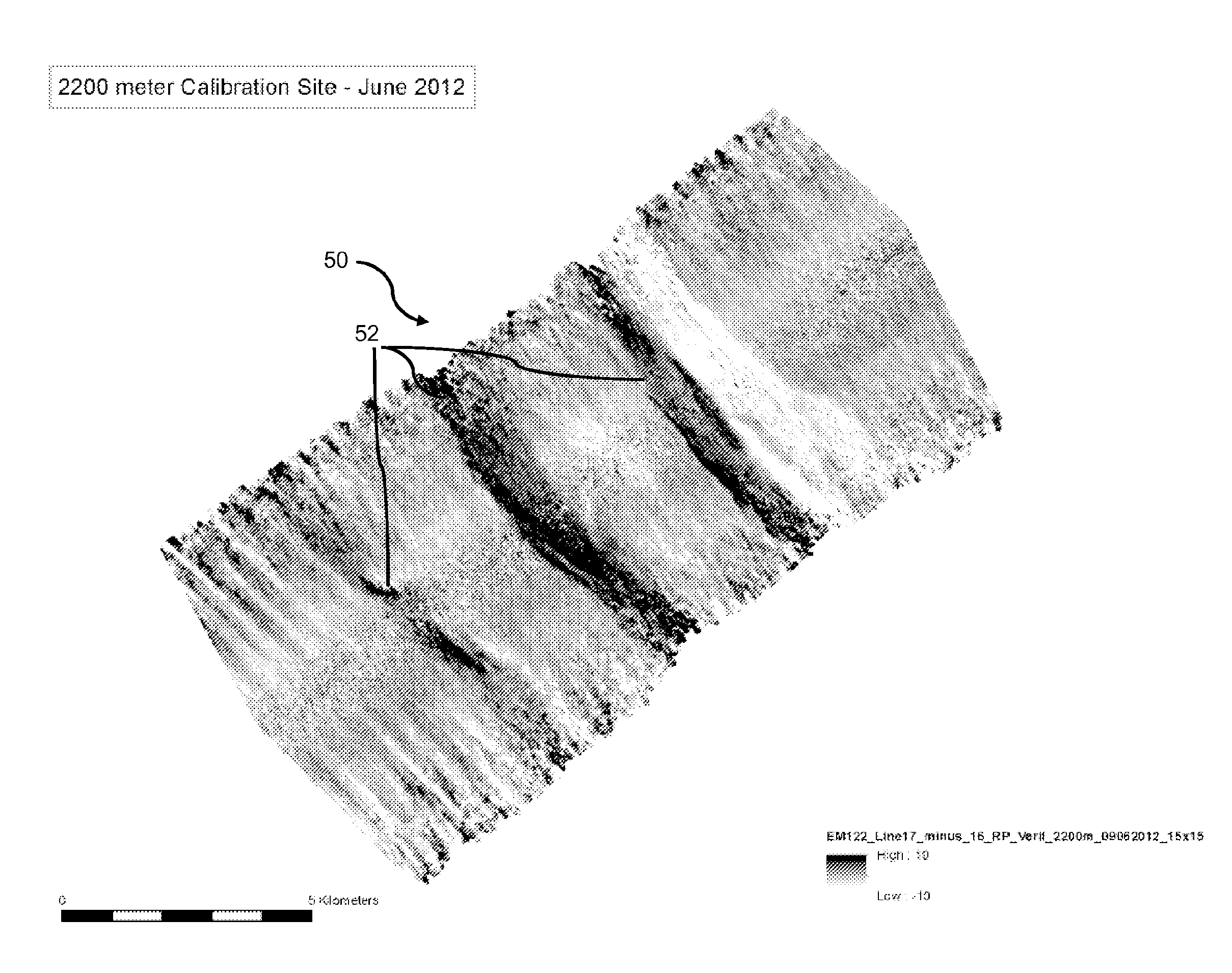
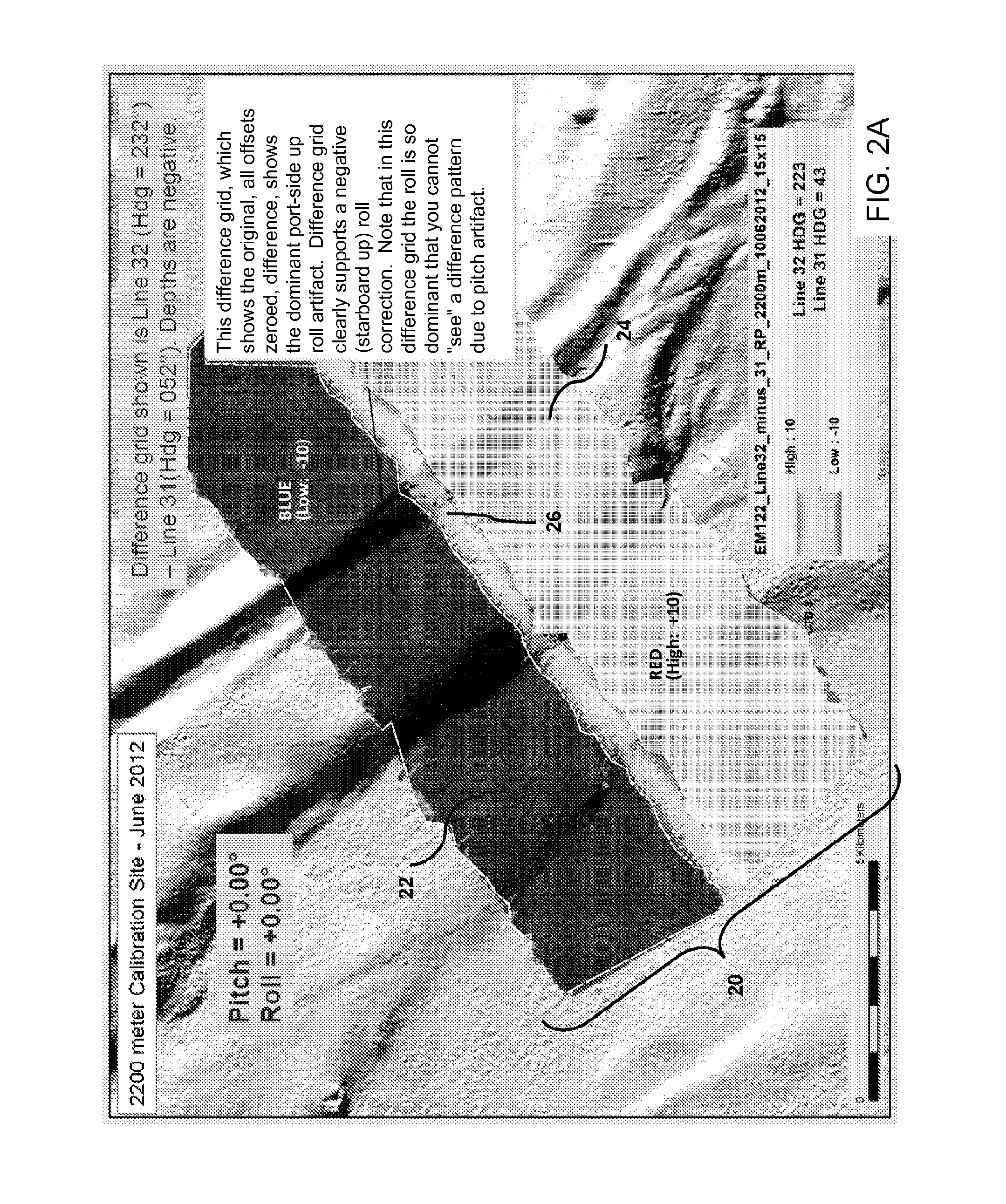
A system and method are provided for visualizing an offset in static parameters in an echo sounding system by generating a difference grid by subtracting a first survey line from a second survey line to determine difference values at each point in the grid; and displaying the difference grid on a display device, where the difference values are represented on a visual scale. The difference values may be used to calibrate the echo sounding system or check the quality of the calibration of an echo sounding system.

Description

RELATED APPLICATIONS[0001]This application claims the benefit of the priority of U.S. Provisional Application No. 61 / 786,521, filed Mar. 15, 2013, which is incorporated herein by reference in its entirety.FIELD OF THE INVENTION[0002]The present invention relates to a system and method for improving the calibration and / or checking the calibration of acoustic imaging systems for mapping the floor of a body of water.BACKGROUND OF THE INVENTION[0003]Echo sounding systems, which are widely used for underwater imaging, work by transmitting a sound pulse or “ping” at a specific frequency, and then receiving that same pulse through a receiver. The received signal is input into a computer processor that determines how long it takes to receive the returning pulse. This delay is translated into depth. The processing system assigns a color range or grey scale for depth to create a 2D or 3D top-side model of the seafloor. U.S. Pat. No. 5,485,432 of Aechter et al., incorporated herein by referenc...

Claims


Application Information

Patent Timeline
IPC IPC(8): G01S7/52G01S15/89G01S15/87G01S7/62G01S15/02
CPCG01S7/52004G01S7/6263G01S15/89G01S15/87G01S15/025G01S15/86
Inventor ORANGE, DANIEL L.
Owner ORANGE DANIEL L
Why Eureka
Try Eureka