Connector and Substrate Interconnection Structure

a technology of interconnection structure and connector, which is applied in the direction of coupling contact member, coupling device connection, electrical apparatus, etc., can solve the problems of degrading the reliability of connection between the connector and the connection object, wear in the sliding portion of the terminal, etc., to reduce the wear of the terminal, prevent excessive movement, and absorb greater vibration

Active Publication Date: 2016-10-06
IRISO ELECTRONICS CO LTD
View PDF7 Cites 25 Cited by
  • Summary
  • Abstract
  • Description
  • Claims
  • Application Information

AI Technical Summary

Benefits of technology

[0015]The present invention also provides a connector electrically connected to a connection object. The connector includes an engagement-side housing engaged with the connection object; a substrate-side housing secured to a substrate; and a first terminal having a first contact portion in electrical contact with the connection object engaged with the engagement-side housing, and a movable piece configured to support the substrate-side housing such that the substrate-side housing can be displaced with respect to the engagement-side housing in engaging and disengaging directions of the connection object with respect to the engagement-side housing, while maintaining the contact of the first contact portion with the connection object.
[0016]The present invention also provides a connector that includes a first connector and a second connector electrically connected to the first connector. The first connector includes an engagement-side housing engaged with the second connector; a substrate-side housing secured to a substrate; and a first terminal having a first contact portion in electrical contact with a second terminal of the second connector engaged with the engagement-side housing, and a movable piece configured to support the substrate-side housing such that the substrate-side housing can be displaced with respect to the engagement-side housing in engaging and disengaging directions of the second connector with respect to the engagement-side housing, while maintaining the contact of the first contact portion with the second terminal of the second connector.
[0017]If the substrate vibrates in the engaging and disengaging directions of the first connector and the second connector or connection object, the substrate-side housing is displaced in response to the vibration. However, in the connector of the present invention, the movable piece allows the substrate-side housing to be displaced with respect to the engagement-side housing. Since the movable piece can thus absorb the vibration, it is possible to maintain the electrical contact of the first contact portion with the second connector or connection object. Therefore, when the substrate vibrates in the engaging and disengaging directions of the connection object, it is possible to more effectively reduce wear of the terminals and absorb greater vibration than in the related art where vibration is absorbed only by sliding of the first contact portion with respect to the second connector or connection object.
[0018]In the connector according to the present invention, the engagement-side housing may have an abutting portion configured to abut against the substrate to which the substrate-side housing is secured.
[0019]In the connector according to the present invention, the engagement-side housing may have an abutting portion configured to abut against the substrate-side housing.
[0020]Thus, even when, in the engaging operation, the engagement-side housing is pressed toward the substrate or the substrate-side housing by the second connector or connection object, the abutting portion can abut against the substrate or the substrate-side housing to prevent excessive movement.

Problems solved by technology

In this electric connector, repeated application of vibration in the mating and unmating directions may cause wear in sliding portions of terminals.
This may degrade the reliability of connection between the connector and the connection object.

Method used


Image

  • Connector and Substrate Interconnection Structure
  • Connector and Substrate Interconnection Structure
  • Connector and Substrate Interconnection Structure

Examples


first embodiment

FIGS. 1 to 22

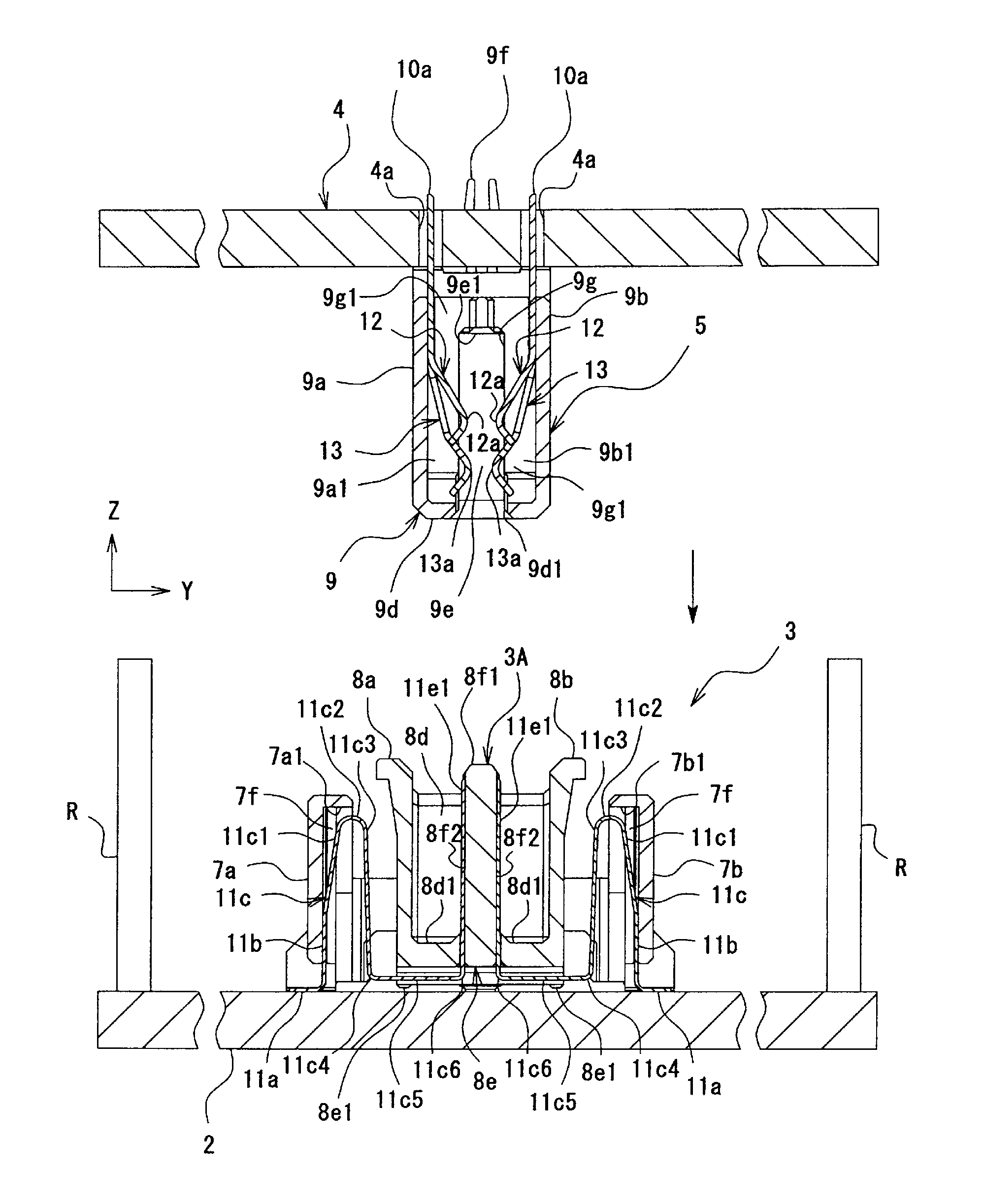
[0066]As illustrated in FIG. 16, the electric connector 1 of the first embodiment includes the plug connector 3 serving as a “first connector” mounted on the first substrate 2, and the socket connector 5 serving as a “second connector” or “connection object” mounted on the second substrate 4. The first substrate 2 and the second substrate 4 are electrically connected to each other by bringing the plug connector 3 and the socket connector 5 into engagement.

(Plug Connector)

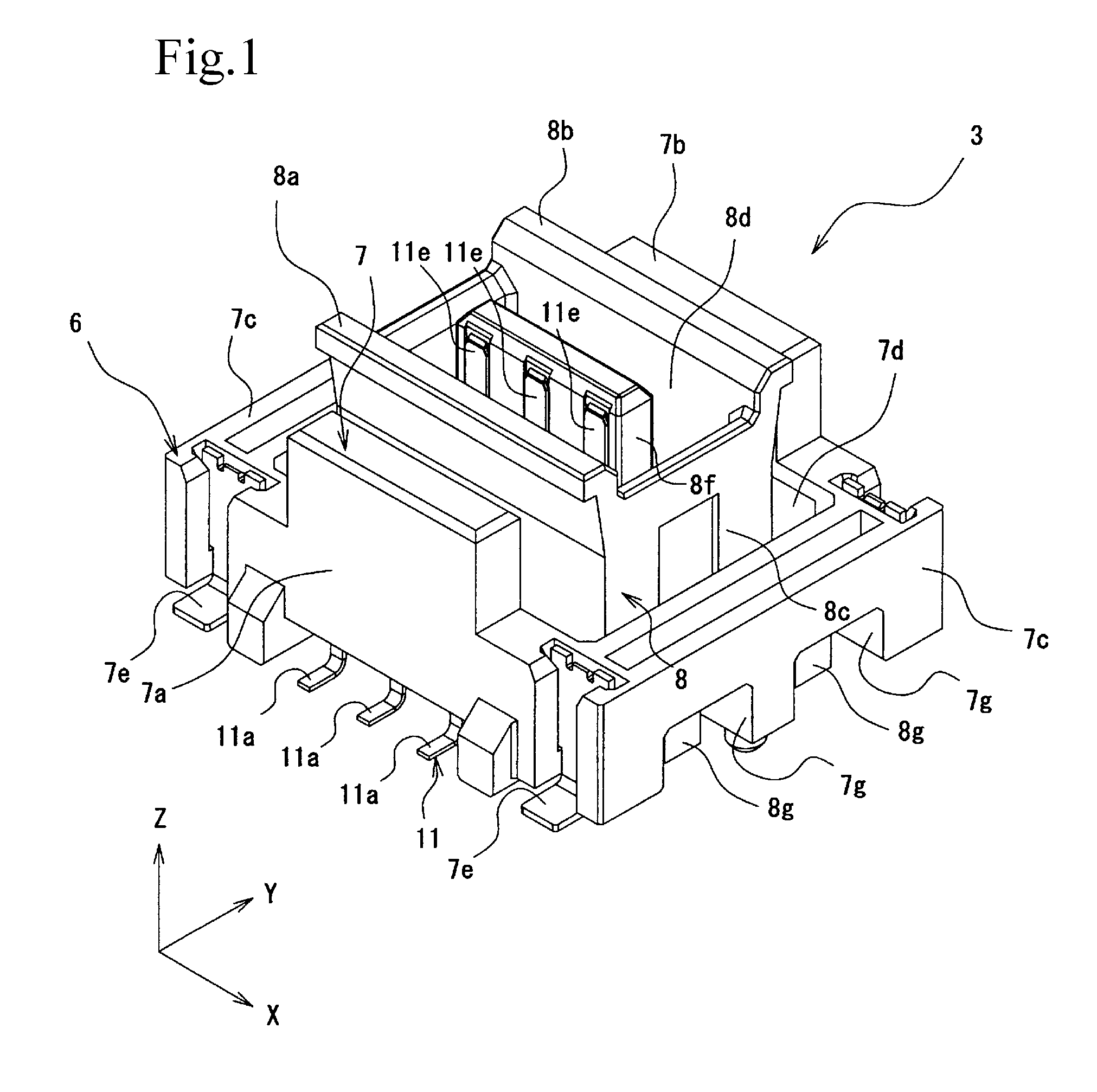
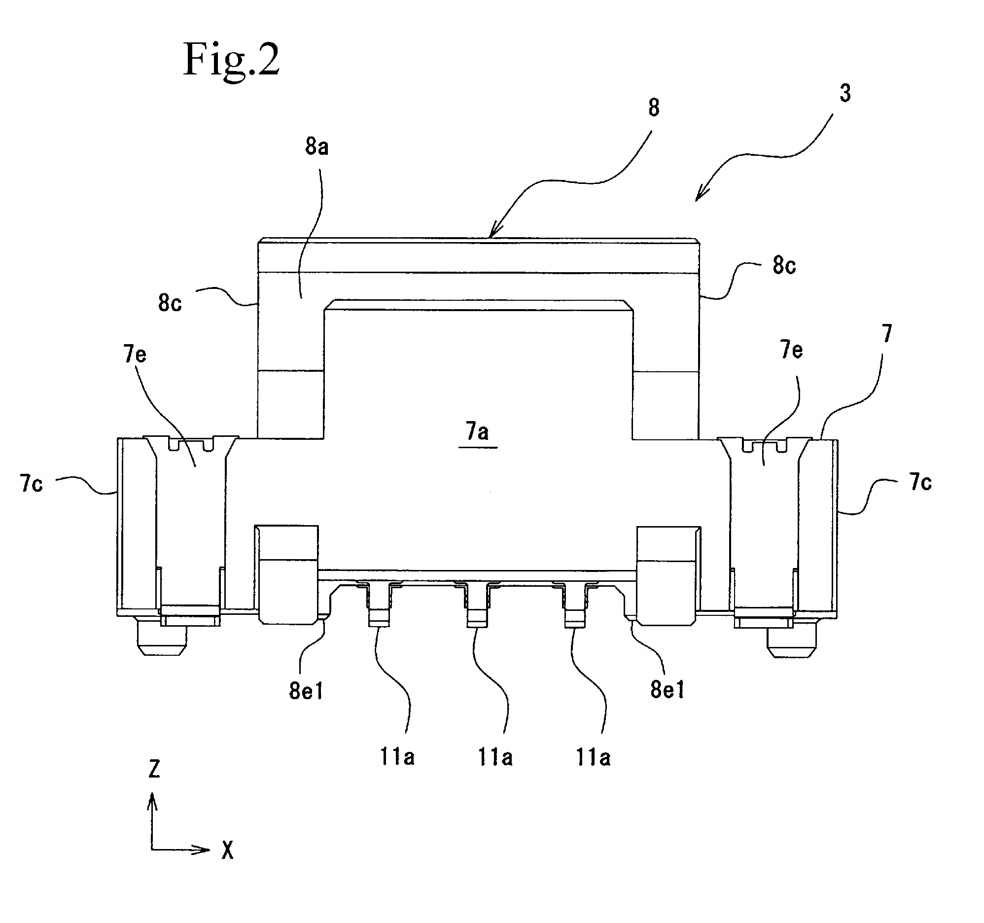
[0067]As illustrated in FIGS. 1 to 5, the plug connector 3 of the present embodiment includes a plug housing 6 and the plug terminals 11 each serving as a “first terminal”. The plug connector 3 is a surface mount connector. The plug connector 3 is electrically connected to the first substrate 2 by being mounted on a planar surface of the first substrate 2.

(Plug Housing)

[0068]The plug housing 6 is a molded component of insulating resin. The plug housing 6 is a floating connector including a fixed housing...

second embodiment

FIGS. 23 to 25

[0140]The first embodiment describes the electric connector 1 in which the plug terminals 11 have the movable parts 11c. An electric connector 21 according to a second embodiment includes a socket connector 25 serving as a “first connector” secured to the first substrate 2, and a plug connector 23 serving as a “second connector” secured to the second substrate 4. The socket connector 25 includes a socket housing 29 including a fixed housing 27 serving as a “substrate-side housing” and a movable housing 28 serving as an “engagement-side housing”, and socket terminals 30 each serving as a “first terminal” having a movable part 30c serving as a “movable piece”.

[0141]Also, the first embodiment describes the electric connector 1 in which the front contact point 13a and the rear contact point 12a of each socket terminal 10 are brought into electrical contact with the corresponding plug terminal 11 from one side. On the other hand, in the electric connector 21, a plurality of...

third embodiment

FIGS. 26 to 28

[0157]The first and second embodiments provide the electric connectors 1 and 21 in which either the plug terminals or the socket terminals have movable parts. A third embodiment provides an electric connector 41 in which the plug terminals 51 and the socket terminals 50 have movable parts 51c and 50c, respectively. Thus, a large vibration can be fully absorbed by the movable parts 51c of the plug terminals 51 and the movable parts 50c of the socket terminals 50. Also, since the electric connector 41 has the movable parts 50c and 51c, the amount of movement required to absorb vibration can be distributed between the movable parts 50c and 51c. Therefore, as compared to the case where only the plug terminals or the socket terminals have movable parts, a load applied to each movable part can be reduced, and hence it is possible to reduce plastic deformation of and damage to the movable parts.

[0158]In the electric connector 41 of the present embodiment, a socket connector 4...


PUM


Abstract

A plug connector electrically connected to a socket connector includes a movable housing engaged with the socket connector; a fixed housing secured to a first substrate; and a plug terminal having a plug contact portion in electrical contact with the socket connector engaged with the movable housing, and a movable part configured to support the fixed housing such that the fixed housing can be displaced with respect to the movable housing in engaging and disengaging directions of the socket connector with respect to the movable housing, while maintaining the contact of the plug contact portion with the socket connector.

Description

BACKGROUND OF THE INVENTION[0001]1. Field of the Invention[0002]The present invention relates to a connector configured to bring a substrate and a connection object into electrical contact, and also relates to a substrate interconnection structure including the connector.[0003]2. Description of the Related Art[0004]Among electric connectors including a connector electrically connected to a substrate and a connection object engaged with the connector are those in which terminals of the connector each have a movable part for absorbing vibration. The movable part is provided between a substrate connection portion secured to the substrate and a contact point in electrical contact with the connection object. When a vibration occurs, the movable part elastically deforms to absorb the vibration, thereby maintaining the electrical contact between the contact point and the connection object (see, e.g., Japanese Unexamined Utility Model Registration Application Publication No. 7-32878).[0005]...

Claims


Application Information

Patent Timeline
Patent Type & Authority Applications(United States)
IPC IPC(8): H01R13/533H01R13/502H01R12/71
CPCH01R13/533H01R13/502H01R12/716H01R12/51H01R13/6315H01R13/24H01R12/91H01R13/26H01R13/187
Inventor KOBAYASHI, HIROAKIOGURA, YOSHIYUKISATO, KATSUMASAKUNIYOSHI, KOJI
Owner IRISO ELECTRONICS CO LTD
Why Eureka
Try Eureka