Fluid conveyance monitoring system in an extracorporeal blood treatment device

a monitoring system and blood treatment technology, applied in medical devices, instruments, mechanical devices, etc., to achieve the effect of increasing the occurrence of haemolysis

Active Publication Date: 2016-10-13
B BRAUN AVITUM
View PDF3 Cites 4 Cited by
  • Summary
  • Abstract
  • Description
  • Claims
  • Application Information

AI Technical Summary

Benefits of technology

[0008]Based on the state of the art described above, an object of the present invention is to eliminate the above-mentioned disadvantages, in particular to create a method for the monitoring of the conveyance of fluid and in the broadest sense a method for the conveyance of fluid in which incomplete wear of the cross-section of the fluid line and delayed transition from occluded to non-occluded, in particular wear or error, can be detected reliably and quickly, thereby minimizing the risk of haemolysis.
[0010]Using the method according to aspects of the invention, it is possible to detect the lack of closure of the cross-section of the fluid line in a particularly advantageous and simple manner. This can occur, for example, as a result of wear or failure of the squeeze elements and / or the elements pre-tensioned against the fluid line such as springs. What is more, the method according to aspects of the invention can be used to detect wear or ageing of the fluid line, e.g. slackening or bending, especially on the arterial side. Finally, the method can be used to ensure that fluid is conveyed in such a way that an opening of the conveyance volume section when a squeeze element exits the conveyance path, i.e. the transition from occluded to non-occluded, is geared as effectively as possible towards the avoidance of the return flow of fluid from the high-pressure side into the conveyance volume section while at the same time not pressing the squeeze elements too hard against the fluid line so as to avoid excessive wear. It is now possible, in order to avoid haemolysis, to coordinate the squeeze elements and the support surface, also referred to as the pump bed, in such a way that during rotation the transition between the states occluded and non-occluded is effected as quickly as possible. When the state is occluded, it is possible to ensure that the occlusion is as tightly sealed and sustained as possible. On the other hand, it is also possible to ensure that the occlusion is not too hard so as to minimize wear in the pump segment.
[0016]The invention can especially be used to achieve the following advantages:
[0017]reduction or avoidance of haemolysis which is harmful to blood, since defective closing of the cross-section of the fluid line and defective transition from the occluded to the non-occluded state can be detected simply and quickly,
[0018]a return flow of fluid from the high-pressure area into the conveyance path due to pressure difference can be reduced or avoided in this way, thereby resulting in a reduction or even an avoidance of additional pulsation;
[0033]In all embodiments of the invention, a threshold value can be or have been defined for the detected fluid pressure value at the exceedance of which an error signal is emitted. It is advantageous for an alarm not to be triggered immediately after a single exceedance of the limit value but for several conveyance volume sections to be observed so as to rule out any potential disruptions that may have been recorded such as patient movements or electromagnetic influence on the sensors.

Problems solved by technology

This can occur, for example, as a result of wear or failure of the squeeze elements and / or the elements pre-tensioned against the fluid line such as springs.

Method used


Image

  • Fluid conveyance monitoring system in an extracorporeal blood treatment device
  • Fluid conveyance monitoring system in an extracorporeal blood treatment device
  • Fluid conveyance monitoring system in an extracorporeal blood treatment device

Examples


Embodiment Construction

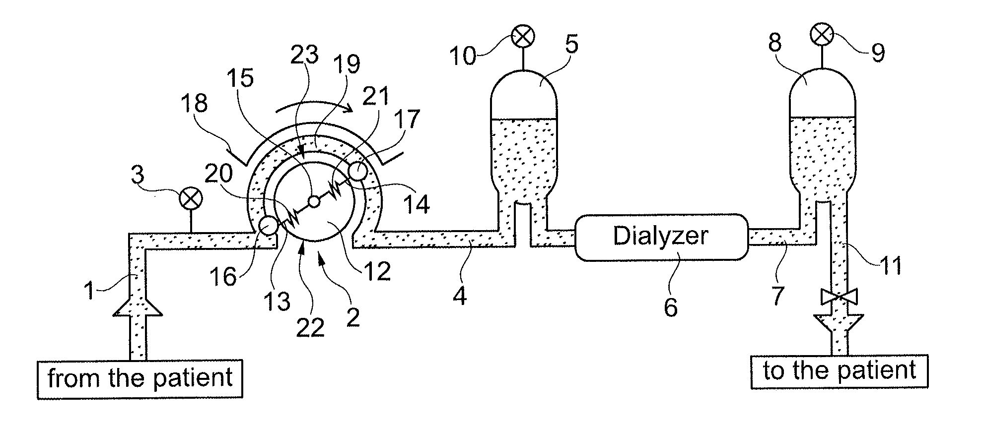
[0042]FIG. 1 shows by way of an example a section of a device for extracorporeal blood treatment which is operated using the method according to aspects of the invention. The entire extracorporeal blood circuit of the device is essentially shown.

[0043]On the low-pressure side this circuit comprises an arterial blood line 1 with which blood is fed from a patient, who is not shown, to a peristaltic pump 2 of the treatment device. Before the peristaltic pump 2, an arterial pressure monitor 3 is provided which measures the pressure before the peristaltic pump 2, i.e., the pressure on the low-pressure or arterial side.

[0044]On the high-pressure side, a line 4 feeds as yet untreated blood under high pressure and contaminated with toxins from the peristaltic pump 2 to a droplet chamber 5 and from there to a dialyzer 6. The latter is fed dialysis fluid on the input side (not shown). In the dialyzer 6, blood is treated in familiar fashion with dialysis fluid, e.g. purified. Used dialysis flu...


PUM

PropertyMeasurementUnit
pressureaaaaaaaaaa
fluid pressureaaaaaaaaaa
volumeaaaaaaaaaa

Abstract

A method for monitoring conveyance of fluid in a device for extracorporeal blood treatment, whereby fluid is conveyed by a peristaltic pump in a fluid system from a low-pressure side to a high-pressure side in that an elastically deformable fluid line positioned between the low-pressure side and the high-pressure side is deformed between a support surface and at least two squeeze elements of a rotor rotating opposite the support surface in such a way that a conveyance volume section is formed between the squeeze elements, whereby a fluid pressure value in the fluid system is detected for the conveyance volume section that is specific to the conveyance volume section, and whereby the detected conveyance-volume-specific fluid pressure value of a conveyance cycle n is compared with the detected conveyance-volume-specific fluid pressure value of a previous conveyance cycle n-x.

Description

CROSS REFERENCE TO RELATED APPLICATIONS[0001]This application claims priority to German application DE 10 2015 105 323.3 filed Apr. 8, 2015, the contents of such application being incorporated by reference herein.FIELD OF THE INVENTION[0002]The invention concerns a method for monitoring a conveyance of fluid, in particular blood, in a device for extracorporeal blood treatment, in particular a dialysis machine, whereby fluid is conveyed with a peristaltic pump in a fluid system from a low-pressure side to a high-pressure side and an elastically deformable fluid line positioned between the low-pressure side and the high-pressure side is deformed between a support surface, in particular a support surface formed by a housing of a peristaltic pump, and at least two squeeze elements of a rotor rotating opposite the support surface, in such a way that between the squeeze elements, in particular between immediately consecutive or immediately neighbouring squeeze elements, a conveyance volum...

Claims


Application Information

Patent Timeline
Patent Type & Authority Applications(United States)
IPC IPC(8): A61M1/26G01L13/00
CPCA61M1/267A61M2205/3331A61M2205/702G01L13/00A61M1/3621A61M60/279A61M60/113A61M60/37A61M1/3639A61M1/367F04B43/1253F04B49/08A61M2205/3351A61M2205/3355F04B43/1261F04B49/065
Inventor RITTER, KAI-UWESCHLEICHER, CHRISTIAN
Owner B BRAUN AVITUM
Why Eureka
Try Eureka