Bumped dilator tip

a dilator tip and tip technology, applied in the field of dilators and sheaths, can solve the problems of deformation (damage), trauma to patients, damage to the sheath, etc., and achieve the effect of preventing the tip deformation

Active Publication Date: 2016-10-13
TELEFLEX MEDICAL INC
View PDF1 Cites 2 Cited by
  • Summary
  • Abstract
  • Description
  • Claims
  • Application Information

AI Technical Summary

Benefits of technology

[0017]Briefly stated, the disclosure provides a dilator with a tip that has a bump, an assembly comprising the dilator and a sheath, and methods of use, where the bump on the tip is configured to reduce or minimize damage to the sheath, and to prevent trauma to a patient during insertion or removal.

Problems solved by technology

Where a dilator sheath assembly is inserted into a patient, the force of insertion can result in damage to the sheath, where damage occurs at the point of transition.
The damaged medical instrument, in turn, can cause trauma to the patient, during continued insertion or during removal of the sheath from the patient.
In other words, trauma can occur to tissue where insertion of the dilator-sheath assembly results in deformation (damage) of the sheath tip, where continued attempts to insert or withdraw the damaged sheath can traumatize the tissue.
No matter how small the radius or acute the lead angle of the distal tip of the sheath, catheter, or trocar, the transition can result in resistance and snagging as it progresses through the tissue and vessel wall.
Furthermore, attempts to improve insertion by making the distal taper of the sheath thinner have led to buckling or deforming of the sheath tip during insertion.
Trauma, insult, and injury, are often issues that require management and longer hospital time.
The practitioner conventionally has had to place a thumb or finger over the proximal opening of the sheath to prevent blood loss and air embolism; however, this restricts the practitioner's hand movement, and is not a reliable method.

Method used


Image

  • Bumped dilator tip
  • Bumped dilator tip
  • Bumped dilator tip

Examples


example 1

[0113]The following example involved thin film testing. Comparative testing of three different sheath tips was conducted, where the tests were conducted with a thin polymer film (FIGS. 5 and 6). The thin polymer film was 0.015 inch thick natural polyurethane from Stevens Urethane P / N ST-1880 (Easthampton, Mass.). Insertion force was measured with an MTS Universal Testing Machine with a 50 Newton (N) load cell. The test stand advances the sheath-dilator assembly through the film at a controlled rate. The film was perforated with a needle prior to insertion. The needle was a 21 GA introducer needle. Testing was with an assembled dilator-sheath. The three tips that were tested were as follows:

[0114](1) A preferred embodiment sheath tip (45 degree chamfer) (gmf) (squares),

[0115](2) Predicate sheath tip (gmf) (diamonds), and

[0116](3) Competitor sheath tip (gmf) (solid dots) (FIG. 5).

[0117]The insertion force is shown in units of gmf. The sheaths were identical for the preferred embodimen...

example 2

[0124]The following example used porcine skin testing. The potential for sheath tip deformation upon insertion through porcine tissue was measured. What was compared was insertion of the standard sheath and dilator and the standard sheath with a non-limiting preferred embodiment (45 degree chamfer) dilator and the predicate dilator. The non-limiting preferred embodiment (45 degree chamfer) dilator allowed for 29 / 31 sheaths to be inserted through the porcine tissue without any damage. But with the standard dilator, the standard dilator only allowed 6 / 32 sheaths to be inserted without any damage. This represents a 75% improvement in performance, or a 59%-91% improvement with 95% confidence.

Test Medium

[0125]Porcine skin collected from pig feet was used for testing. Animals aged about 2 years yield usable skin. The skin was from Animal Technologies, Inc. (Tyler, Tex. 75702). Skin is delivered either fresh, on ice, or frozen. Porcine skin from other areas on the body as well as other ani...

example 3

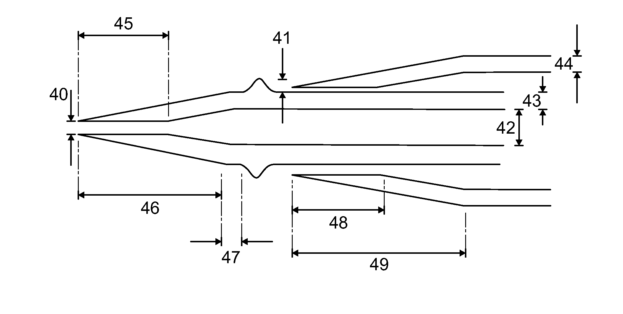
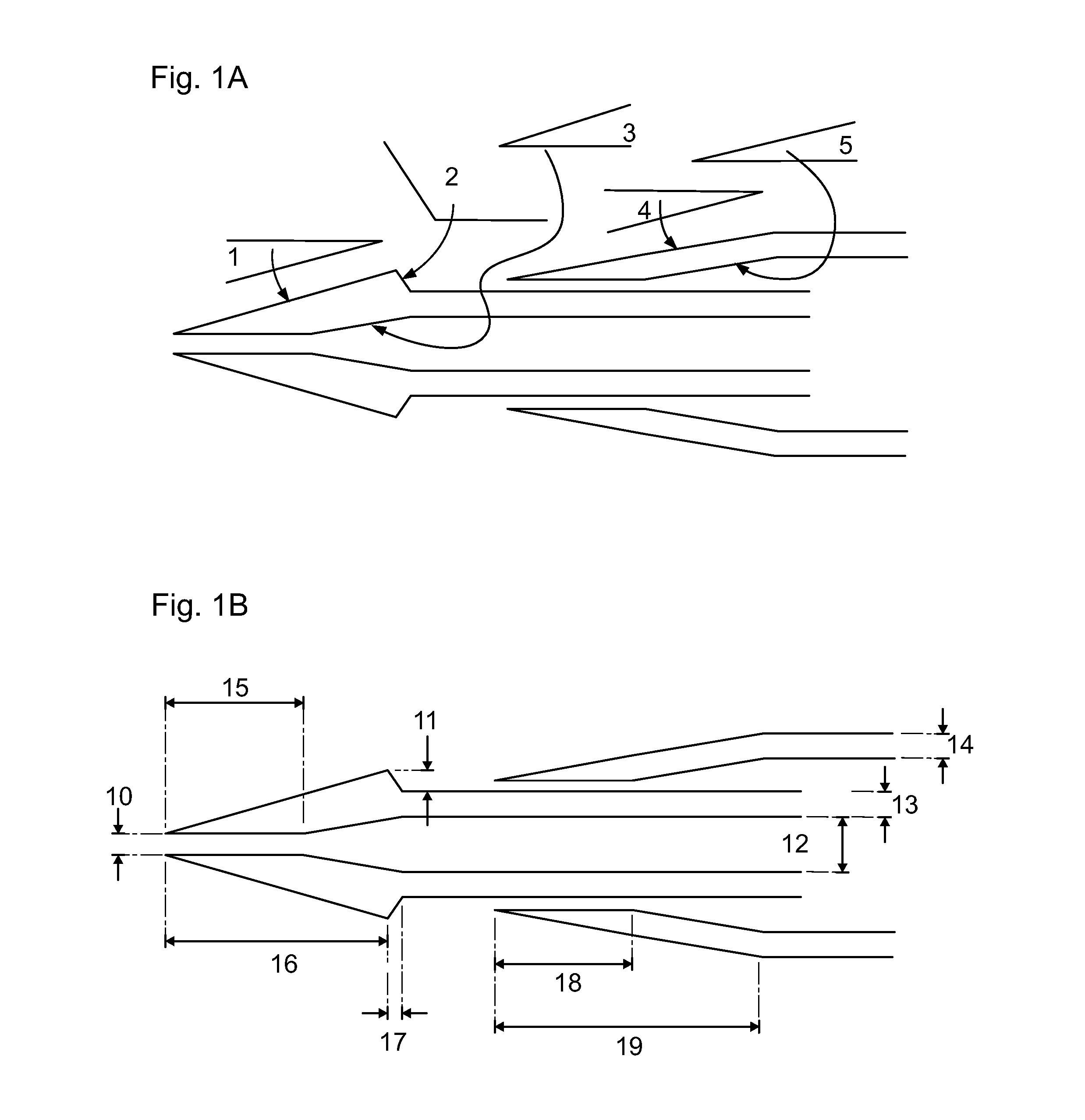
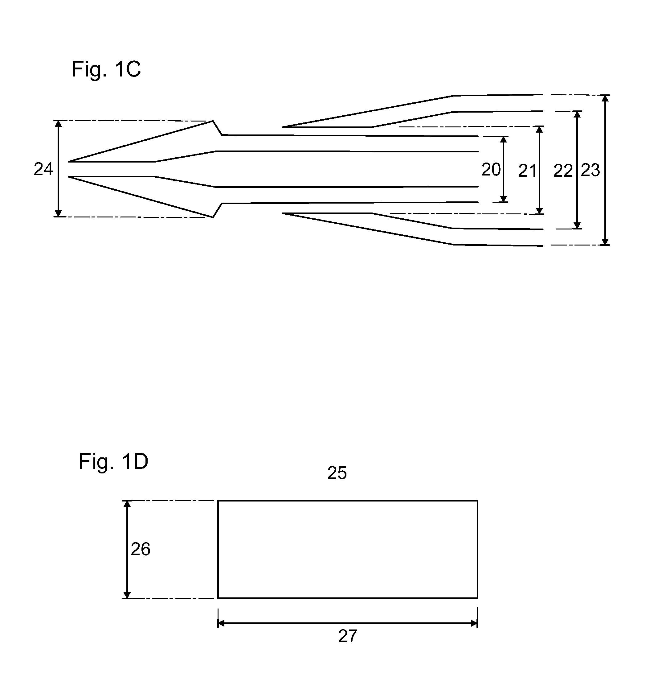
[0137]A 3-dimensional diagram of a generic embodiment is disclosed in FIG. 7. Starting from the distal end, (71) is the sheath tip, (72) is the sheath body, (73) is the sheath housing (also called sheath hub), (74) indicates the general position of the sheath aperture (not visible in this view, but visible when viewed from the proximal end), (75) is the dilator tip, (76) is the dilator bump (also called radially enlarged dilation member), (77) is the dilator shaft (also called elongate dilator shaft), and (78) is the dilator hub or coupler. The fin in the dilator hub and the groove in the sheath hub is a non-limiting coupling mechanism.


PUM

PropertyMeasurementUnit
angleaaaaaaaaaa
angleaaaaaaaaaa
angleaaaaaaaaaa

Abstract

The disclosure provides a dilator with a tip that has a bump, an assembly comprising the dilator and a sheath, and methods of use, where the bump on the tip is configured to reduce or minimize damage to the sheath, and to prevent trauma to a patient during insertion or removal.

Description

[0001]This application claims the full Paris Convention benefit of, and priority to U.S. Provisional Application No. 61 / 586,649, filed Jan. 13, 2012, entitled Novel Bumped Dilator Tip, which is incorporated herein by reference, as if fully set forth in its entirety.FIELD OF THE DISCLOSURE[0002]The disclosure relates to systems, methods, and devices for vascular access. In particular, the disclosure relates to dilators and sheaths, and assemblies thereof, as well as to related medical devices such as catheters, cannulae, introducers, trocars, dilation instruments, guide wires, rapid exchange systems, hubs, couplers, and valves, as well as known and any later developed emplacement apparatus and methods.BACKGROUND OF THE DISCLOSURE[0003]In medical practice, the introduction of drugs or instruments into a patient sometimes involves a device known as a dilator sheath assembly. The dilator and sheath each resemble a tube, where the dilator fits into the sheath, and where a narrow distal t...

Claims


Application Information

Patent Timeline
Patent Type & Authority Applications(United States)
IPC IPC(8): A61M29/02
CPCA61M29/02A61M2025/0681Y10T29/49826A61M29/00A61B17/34A61B17/3417A61B17/3421A61B17/3439A61M25/0662
Inventor AMAN, MICHAELWEINLICK, DANIEL
Owner TELEFLEX MEDICAL INC
Why Eureka
Try Eureka