
Sports bag with integral transportation system

a transportation system and sports bag technology, applied in the field of sports bags with integrated transportation systems, can solve the problems of personal items adding substantial weight to golf bags, affecting the performance of golfers, and requiring considerable physical effort by golfers, and achieve the effect of convenient mounting of bags

Inactive Publication Date: 2014-07-01
GOLF N GO
View PDF53 Cites 15 Cited by
  • Summary
  • Abstract
  • Description
  • Claims
  • Application Information

AI Technical Summary

Benefits of technology

The patent describes a golf bag with a structural system that includes horizontal bands and vertical rods that provide support and rigidity to the bag. The bag also has multiple wheels, which allow for better mobility and stability when walking the golf course. The technical effects include improved protection and stability of the bag, increased efficiency and ease of transport, and reduced damage to golf courses.

Problems solved by technology

The storage of clubs, golf accessories, and personal items adds substantial weight to golf bags and often creates heavy loads for golfers to lift, move, carry, or otherwise transport about the golf course.
Golfers expend considerable physical effort, in addition to expense, in avoiding the burdens of manually lifting, carrying, moving, and / or transporting their golf bags around a golf course.
Although wheels can be mounted to the base of golf bags in a permanently fixed and exposed location, such wheels are awkward in appearance.
Additionally, such wheels can be hazardous, especially when golfers insert or remove these wheeled bags from trunks or storage hatches of vehicles.
Additionally, golf bags with wheels in permanently fixed and exposed positions generally do not fit within the recessed areas of typical platforms of motorized golf carts.
Wheels which are permanently fixed and exposed also create bulky and irregular shapes making it difficult to store such golf bags in conventional storage stands, racks, bins, lockers, trunks, platforms or other similar storage configurations found in and around golf courses.
Additionally, golf bags with permanently fixed and exposed wheels do not fit within travel containers or systems for traditional golf bags.
Stowing the detached wheels and associated equipment within the bag, severely compromises the amount of space within the bag's storage area for clubs.
It also impairs a golfer's ability to remove and re-insert clubs.
Furthermore, a golfer must expend considerable time and effort attaching the wheels and their associated equipment to the bag before starting play, and detaching and storing these items after play is completed.
Such modifications create an excessively bulky and deformed rolling bag bearing little resemblance to traditional golf bags—making the bag substantially greater in weight; difficult to maneuver; and generally unsuitable for the transportation and storage of clubs, golf accessories, and personal items.
Enlarging the bag's length and circumference (in addition to the bag's outer compartments) also causes the breadth of the bag to be so broad, that it cannot fit within the recessed areas of platforms on the rear of motorized golf carts.
Furthermore, the modified bag is dimensionally incompatible with conventional storage stands, racks, bins, lockers, trunks, platforms, and other similar storage configurations typically found in and around golf courses and residences, and also within travel containers and systems for traditional golf bags.
Prior attempts to overcome the challenges faced when incorporating a transportation system into a traditionally shaped golf bag have not been satisfactory.
Presently there is no golf bag with a three or more wheel integral transportation system, and there is no three or more wheel integral transportation system which can be deployed and retracted without requiring the assembly and disassembly of component parts.

Method used


Image

  • Sports bag with integral transportation system
  • Sports bag with integral transportation system
  • Sports bag with integral transportation system

Examples


sliding embodiment

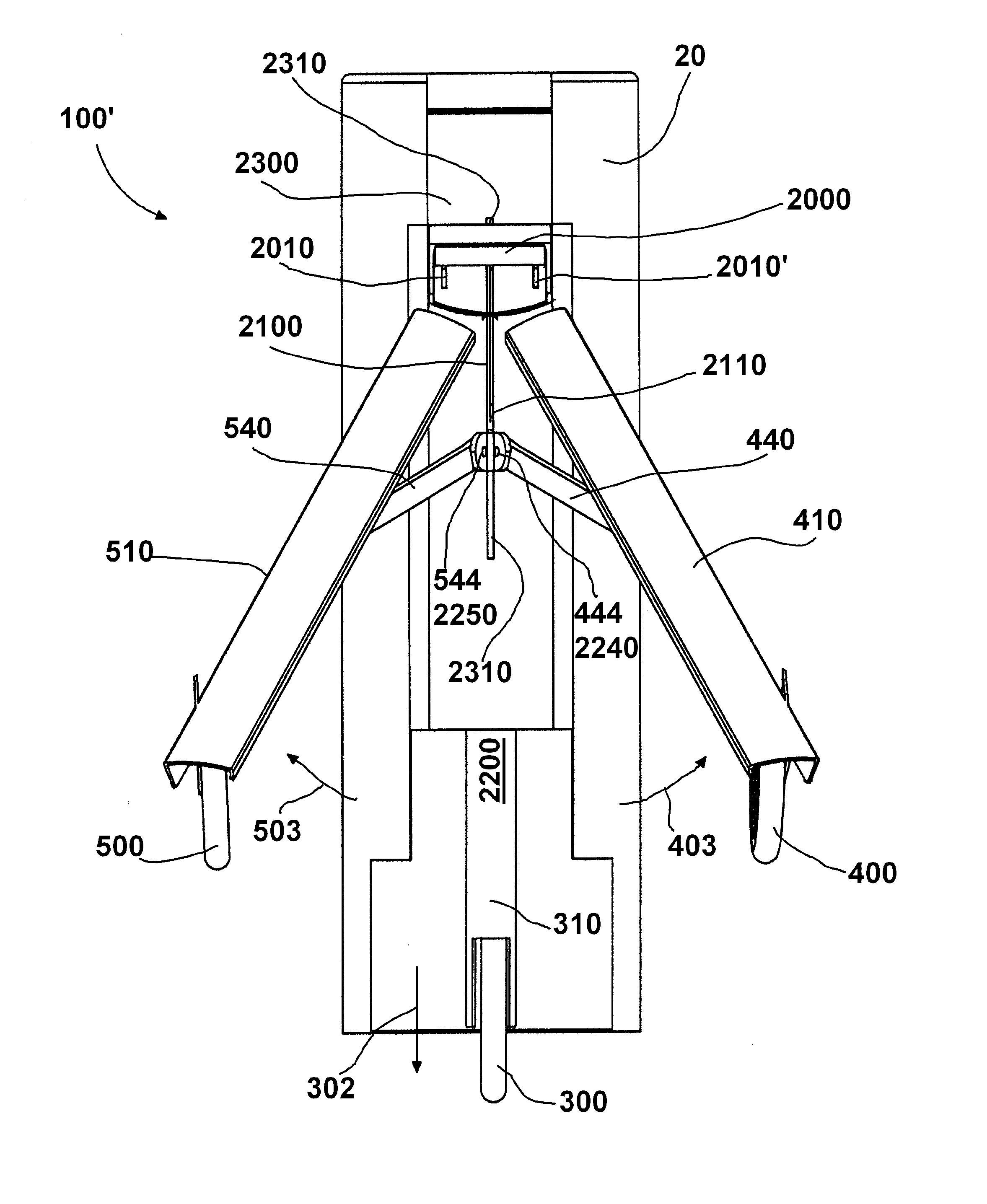
[0110]FIGS. 16-28 show an alternative embodiment of the sports bag with integral transportation system 100′. In these figures the cover 1000 has been omitted for clarity.

[0111]FIG. 16 is a schematic view of another embodiment of the deployment and retraction system 100′ which includes a sliding member 2200 in a sliding housing 2300. FIG. 17 is a side view of the deployment and retraction system 100′ shown in an extended state, where the sliding housing 2300 has been omitted for clarity. FIG. 18 is a side view of a sports bag with integral wheeled transportation system 100′ shown in an extended state. FIG. 19 is a rear view of the deployment and retraction system 100′ shown in an extended state where the sliding housing 2300 has been omitted for clarity. FIG. 20 is a rear view of a sports bag with integral wheeled transportation system 100′ shown in an extended state. FIG. 21 is a top view of the deployment and retraction system 100′ shown in an extended state, where the sliding hous...


PUM


Abstract

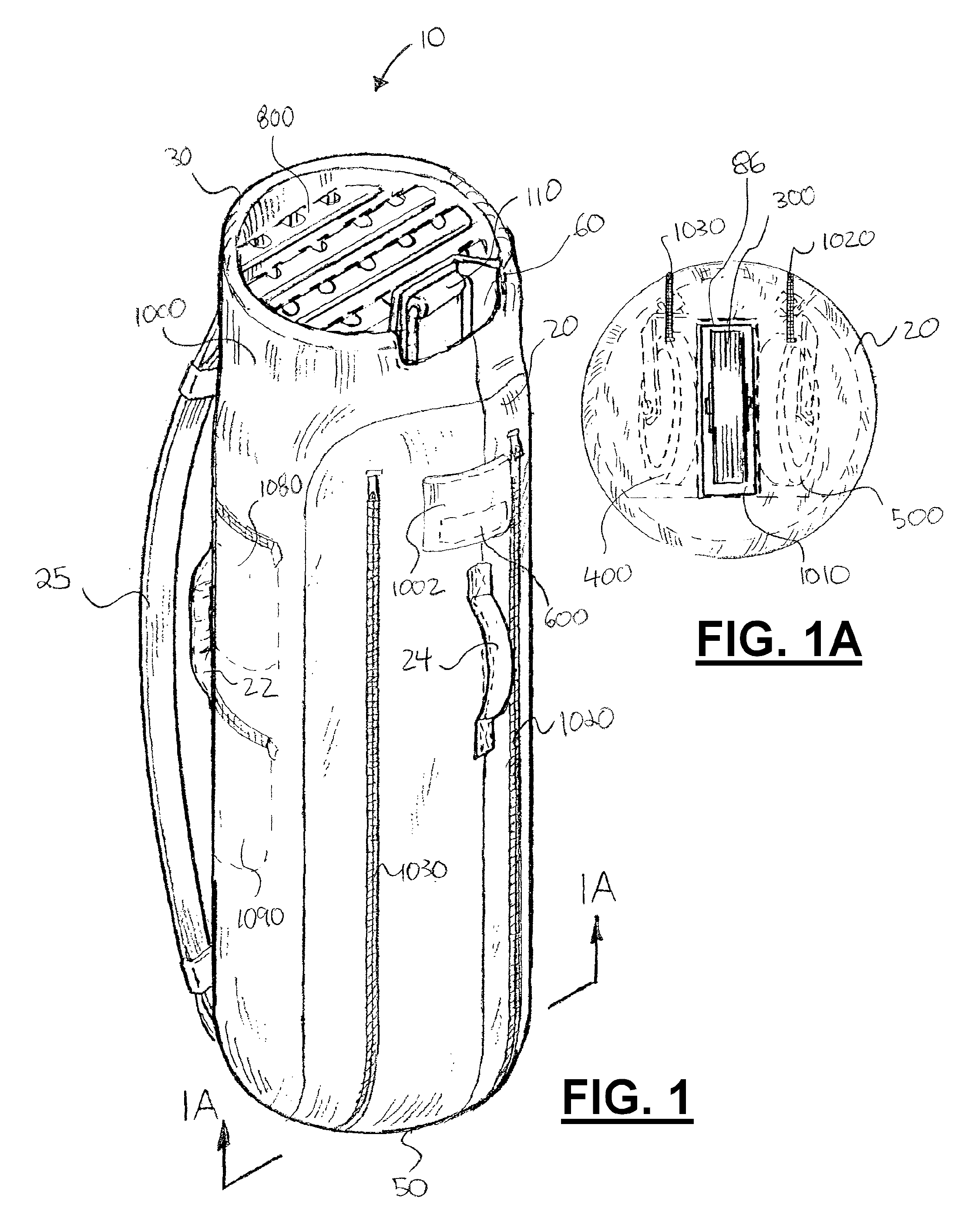
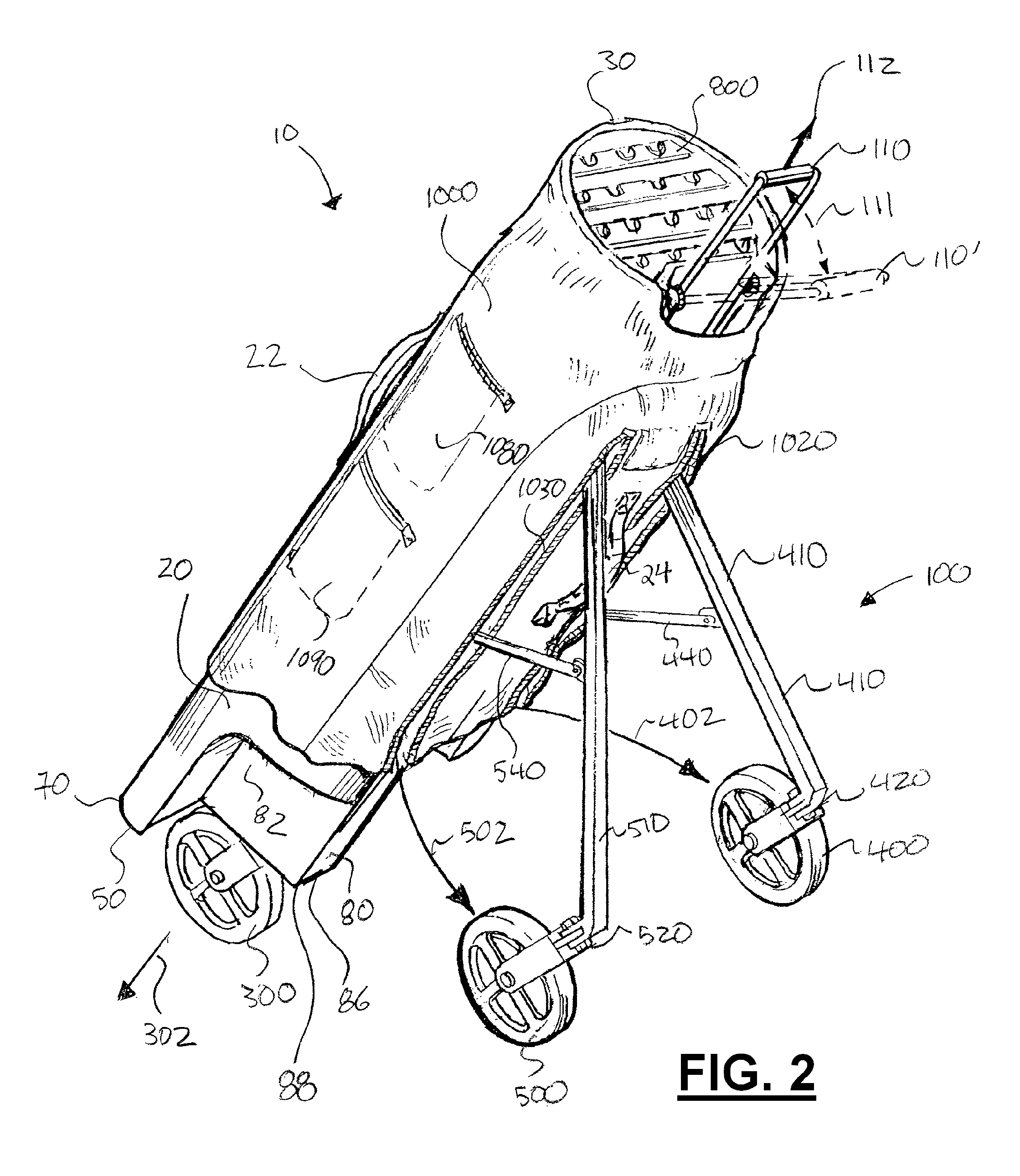
Disclosed is a sports bag assembly with an integral wheeled transportation system. The bag assembly can accommodate the transportation and storage of sports equipment. The wheels can be deployed and retracted with a single mechanical movement, and may be stowed within the geometry of the bag. The bag assembly can fit within the recessed areas of platforms on the rear of motorized golf carts; within conventional storage stands, racks, lockers, vehicle trunks and / or hatches typically found around golf courses and in residences; and within travel containers or other systems for traditional golf bags. The golf bag assembly may also include a ventilated club storage compartment to facilitate the drying of clubs (including grips), and allow drainage of fluids which may enter the interior of the bag assembly. The bag assembly can also include a support and suspension system which restrains the grip and upper shaft or hosel ends of clubs which stabilizes and protects clubs during transport and play. The restraint system also can enhance the golfing experience by reducing or eliminating noise generated by clubs banging together during transportation. The restraint system can also extend the life of golf clubs by preventing contact between clubs, which contact could damage and alter frequency settings for various clubs.

Description

CROSS-REFERENCE TO RELATED APPLICATIONS[0001]This is a continuation-in-part of U.S. patent application Ser. No. 11 / 303,442, filed Dec. 15, 2005, (issuing as U.S. Pat. No. 7,934,729 on May 3, 2011) which was a continuation-in-part of U.S. patent application Ser. No. 11 / 143,936, filed Jun. 3, 2005 (now U.S. Pat. No. 7,287,765), which application was a non-provisional of U.S. Provisional Patent application Ser. No. 60 / 576,620, filed Jun. 4, 2004, and U.S. Provisional Patent application Ser. No. 60 / 618,588, filed Oct. 15, 2004. Priority of each of these applications is hereby claimed and each is incorporated herein by reference.[0002]This is also a continuation-in-part of U.S. patent application Ser. No. 11 / 303,442, filed Dec. 15, 2005, (issuing as U.S. Pat. No. 7,934,729 on May 3, 2011) which was a continuation-in-part of PCT Patent application number PCT / US2005 / 019252, filed Jun. 3, 2005, which was a non-provisional of U.S. Provisional Patent application Ser. No. 60 / 576,620, filed Jun...

Claims


Application Information

Patent Timeline
IPC IPC(8): B62B3/12
CPCB62B3/12A63B55/04B62B1/045A63B55/00Y10S280/06A63B55/08B62B1/042B62B2202/406A63B2210/50A63B55/60A63B55/50A63B55/30
Inventor MURPHY, HOWARD L.GARDNER, THOMAS F.MARSE, DARYL
Owner GOLF N GO
Learn More