Purge device and method of diffusing gas including purge gas

a technology of purge gas and purge device, which is applied in the field of purge, can solve problems such as complex configuration, and achieve the effects of simplifying configuration, reducing the concentration of purge gas, and increasing certain diffusion of purge gas

Active Publication Date: 2016-10-13
MURATA MASCH LTD
View PDF0 Cites 2 Cited by
  • Summary
  • Abstract
  • Description
  • Claims
  • Application Information

AI Technical Summary

Benefits of technology

[0013]Such a purge device is capable of diffusing the gas including the purge gas from a position closer to the opening, enabling more certain diffusion of the purge gas.
[0014]A method of diffusing a gas including a purge gas according to a preferred embodiment of the present invention includes diffusing the gas including the purge gas leaking from the purge device, in a purge device that includes an internal space defined by a chassis, and performs a purge process where an inside of a storage container arranged in the internal space with an article being accommodated, is purged with a purge gas. Air is sent from an outside of the chassis to an area where a gas including the purge gas in the internal space leaks through the opening in the chassis so as to diffuse the gas including the purge gas leaking from the opening.
[0015]In such a method, as air is sent towards the gas including the purge gas leaking from the openings in the chassis, the gas including the purge gas is diffused by the sent air. This lowers the concentration of the purge gas, which prevents an operator from experiencing oxygen deficiency. Furthermore, when air is sent to the gas including the purge gas, since the purge device only requires equipment capable of sending air towards the gas including the purge gas blown out from the openings in the chassis, its configuration is simplified, compared to equipment where the oxygen concentration is kept to a predefined value throughout the inside of the chassis. As a result, this simplified configuration ensures the safety of an operator.
[0016]According to various preferred embodiments of the present invention, operator safety is ensured by using a simplified configuration.

Problems solved by technology

The purge device is enlarged to attain oxygen concentrations with a predetermined value, resulting in its complex configuration.

Method used


Image

  • Purge device and method of diffusing gas including purge gas
  • Purge device and method of diffusing gas including purge gas
  • Purge device and method of diffusing gas including purge gas

Examples


Embodiment Construction

[0024]Preferred embodiments of the present invention will be explained hereinafter with reference to the drawings. In the description of the drawings, the same reference signs are given to the same elements to omit duplicated explanation. The dimension ratio of the drawings does not always match each other.

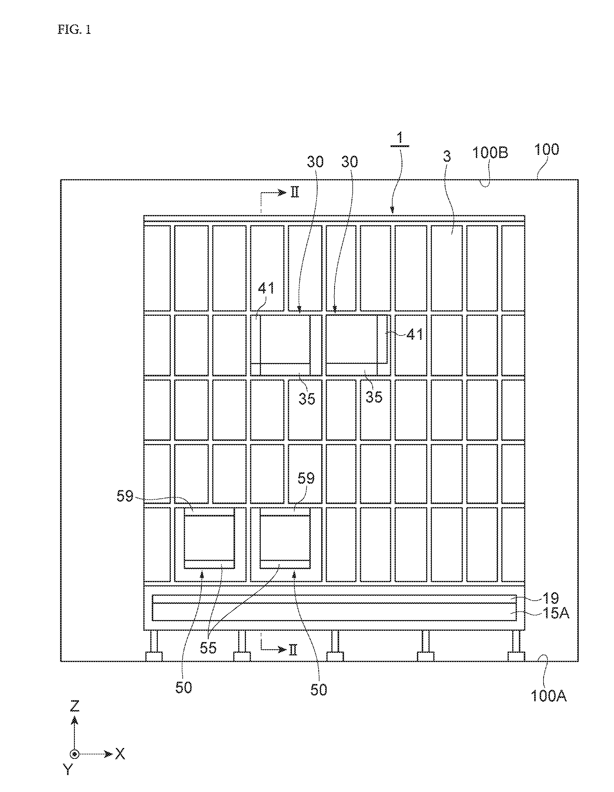
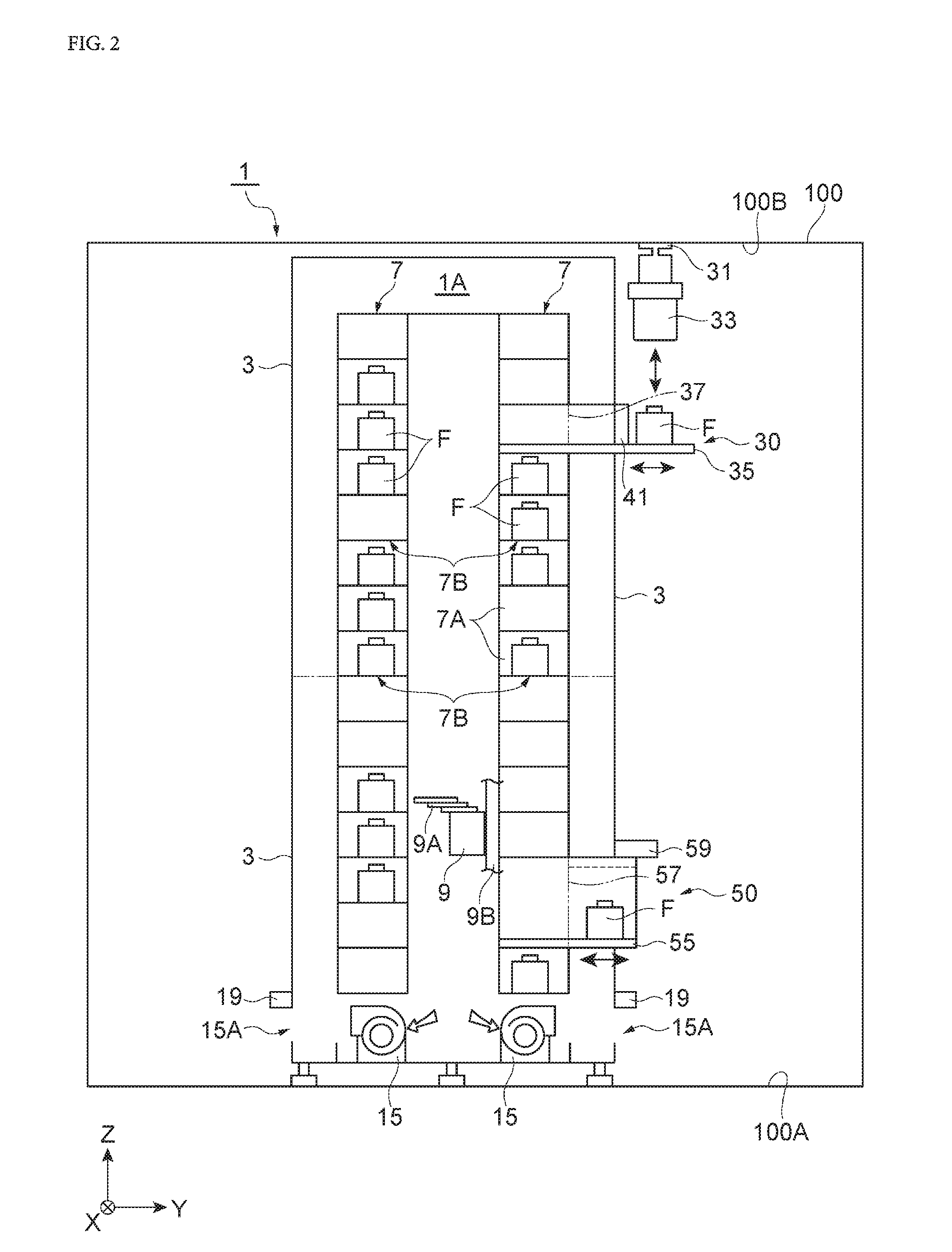
[0025]A purge stocker (purge device) 1 according to a preferred embodiment of the present invention is described below. As shown in FIGS. 1 and 2, the purge stocker 1 includes a purge portion 7B in which the inside of a storage container F such as a FOUP (Front Opening Unified Pod) where an article including a semiconductor wafer or a glass substrate is accommodated is purged with a purge gas, and a storage area 1A that serves as an internal space to store a plurality of storage containers F. As illustrated in FIGS. 1 and 2, the purge stocker 1 is, for example, installed in a clean room 100.

[0026]The purge stocker 1 installed in such a clean room 100 is equipped with a partition (...


PUM


Abstract

A purge device includes an internal space defined by a chassis, and performs a purge process where an inside of a storage container F arranged in the internal space with an article being accommodated is purged with a purge gas. The purge device includes an air blower that is located outside the chassis, and sends air to an area where a gas including the purge gas in the internal space leaks through an opening in the chassis so as to diffuse the gas including the purge gas leaking from the opening.

Description

BACKGROUND OF THE INVENTION[0001]1. Field of the Invention[0002]The present invention relates to a purge device that includes an internal space defined by a chassis, and performs a purge process where an inside of a storage container arranged in the internal space is purged by using a purge gas such as an inert gas or clean dry air, and a method of diffusing the gas including the purge gas that leaks from the purge device.[0003]2. Description of the Related Art[0004]There has been known a purge device that maintains cleanliness by placing a storage container, in which a semiconductor wafer, a glass substrate, or the like is accommodated, in an internal space defined by a chassis and introducing a purge gas into the storage container placed in this internal space (i.e., a so-called purge process). In such a purge device, countermeasures have been taken to prevent an operator from experiencing oxygen deficiency by ventilating the internal space of the purge device to maintain oxygen c...

Claims


Application Information

Patent Timeline
Patent Type & Authority Applications(United States)
IPC IPC(8): B08B9/08B08B5/00H01L21/673
CPCB08B9/08B08B5/00H01L21/67389H01L21/67017H01L21/67769
Inventor MURATA, MASANAOTOKUMOTO, MITSUYAYAMAJI, TAKASHI
Owner MURATA MASCH LTD
Why Eureka
Try Eureka