Improvements relating to lightning protection systems for wind turbine blades

a technology for lightning protection and wind turbine blades, which is applied in the field of lightning protection systems for wind turbine blades, can solve the problems of wind turbines being vulnerable to being struck by lightning, physical damage to turbine blades, electrical damage to the internal control systems of wind turbines,

Active Publication Date: 2016-10-13
VESTAS WIND SYST AS
View PDF6 Cites 17 Cited by
  • Summary
  • Abstract
  • Description
  • Claims
  • Application Information

AI Technical Summary

Benefits of technology

[0010]To allow the reinforced zone to be accessed for electrical connection, the forming element may be provided with a removable element which, when removed, exposes the underlying reinforced zone. However, during the consolidation phase, the removable element beneficially protects the conductive layer from being infused with resin.
[0011]The conductive layer may be any suitable thin sheet-like conductor such as metallic foil or a mesh. However, an expanded metal foil, of copper or aluminium for example, strikes a good balance between electrical conductivity, robustness, weight and cost.
[0012]In order to connect the conductive layer to the electrical component, a connector element may be received through the conductive layer, for example by drilling a hole for its passage. The connector element may be provided with a flat face for mating with a correspondingly flat surface of the reinforced zone which results in a robust electrical contact.

Problems solved by technology

Wind turbines are vulnerable to being struck by lightning; sometimes on the tower, nacelle and the rotor hub, but most commonly on the blades of the turbine.
A lightning strike event has the potential to cause physical damage to the turbine blades and also electrical damage to the internal control systems of the wind turbine.
However, the discrete receptors are relatively complex to install during fabrication of the blade and, moreover, they leave a significant portion of blade area exposed to a risk of lightning strike.
Although a conductive layer used in this way can be said to increase the capability of the lightning protection system to intercept lightning strikes, such a system can be complex to manufacture since the conductive layer must be added to the blade after the blade shell has been fabricated.
This requires an additional time-consuming manufacturing step thereby increasing assembly time and cost.

Method used


Image

  • Improvements relating to lightning protection systems for wind turbine blades
  • Improvements relating to lightning protection systems for wind turbine blades
  • Improvements relating to lightning protection systems for wind turbine blades

Examples


Embodiment Construction

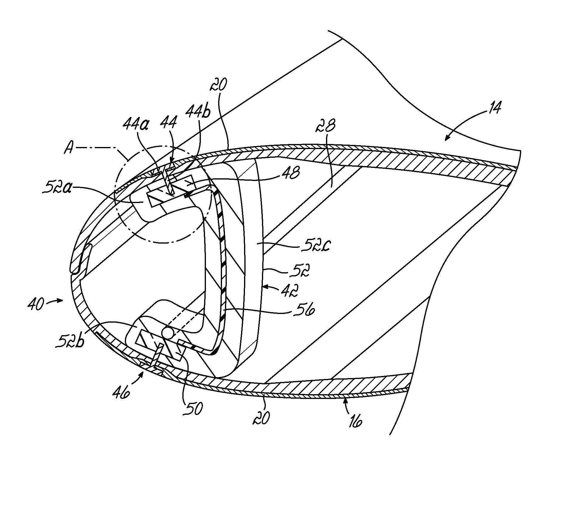
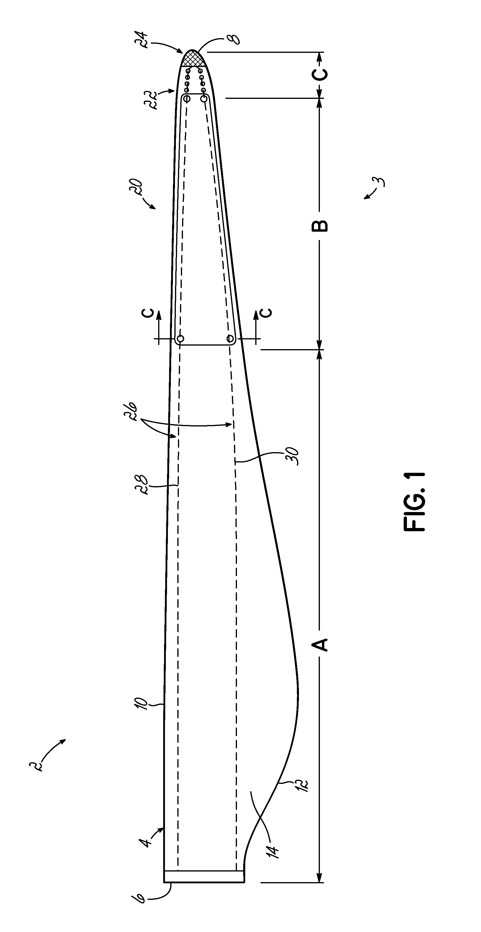
[0027]With reference to FIG. 1, a wind turbine blade 2 incorporates a lightning protection system 3. The blade 2 is formed from a blade shell 4 having two half-shells. The half-shells are typically moulded mainly from glass-fibre reinforced plastic (known as ‘GFRP’ or, simply ‘GRP’) that comprises glass fibre fabric embedded in a cured resin matrix. The precise construction of the blade shell 4 is not central to the invention and so further detailed description is omitted for clarity.

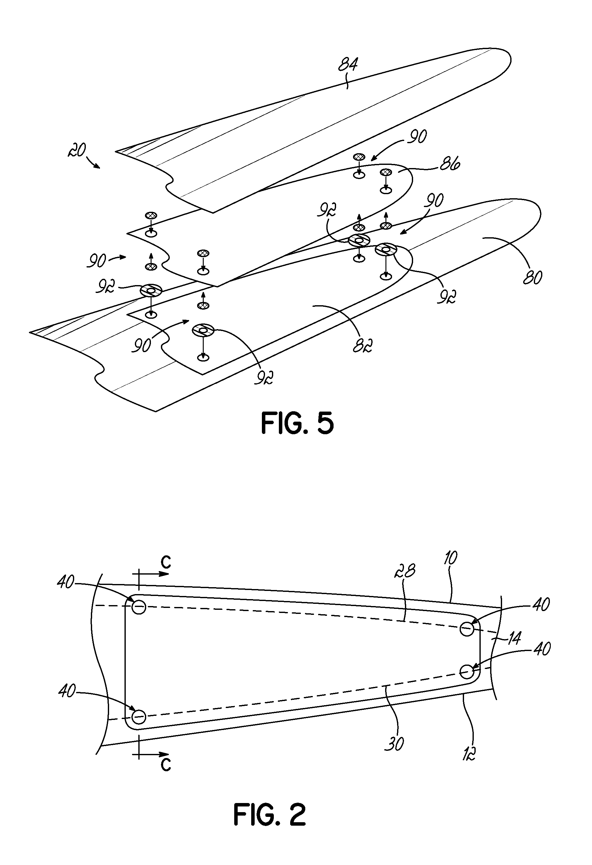
[0028]The blade comprises a root end 6, at which the blade 2 would be attached to a rotor hub of a wind turbine, a tip end 8, a leading edge 10 and a trailing edge 12. A first surface 14 of the blade 2 defines an aerodynamic profiled surface that extends between the leading edge 10 and the trailing edge 12. The blade 2 also includes a second surface also extending between the leading edge 10 and trailing edge 12, which is not shown in the plan view of FIG. 1, but which is indicated as reference numeral ...


PUM

PropertyMeasurementUnit
peak current amplitudesaaaaaaaaaa
thicknessaaaaaaaaaa
thicknessaaaaaaaaaa

Abstract

A method of making a wind turbine blade component incorporating a lightning protection system, the method comprising: providing a mould surface; arranging a forming element on the mould surface; providing an electrically conductive layer; reinforcing the electrically conductive layer in a predetermined region to create a reinforced zone; arranging the electrically conductive layer over the forming element so that the reinforced zone is superimposed on the forming element; arranging one or more structural components on the electrically conductive layer; consolidating the structural components under vacuum to form a blade shell having an integrated electrically conductive layer adjacent an outer surface of the shell; removing at least part of the forming element from the blade shell to define a recess in the outer surface of the shell so as to expose the reinforced zone of the electrically conductive layer; electrically connecting the electrically conductive layer at the reinforced zones to a respective electrical component located adjacent an inner surface of the blade shell. The invention also extends to a preformed component for use in fabricating a wind turbine blade.

Description

TECHNICAL FIELD[0001]The present invention relates to wind turbine blade structures and associated fabrication processes for improving the resilience of wind turbine blades to lightning strikes. The invention also extends to preformed components for use in such wind turbine blades, and methods for fabricating such preformed components.BACKGROUND[0002]Wind turbines are vulnerable to being struck by lightning; sometimes on the tower, nacelle and the rotor hub, but most commonly on the blades of the turbine. A lightning strike event has the potential to cause physical damage to the turbine blades and also electrical damage to the internal control systems of the wind turbine. Wind turbines are often installed in wide open spaces which makes lightning strikes a common occurrence. Accordingly, in recent years much effort has been made by wind turbine manufacturers to design wind turbines so that they are able to manage effectively the energy imparted to them during a lightning strike in o...

Claims


Application Information

Patent Timeline
Patent Type & Authority Applications(United States)
IPC IPC(8): F03D80/30H01B13/00F03D1/06
CPCF03D80/30F03D1/0675F05B2280/10F05B2230/60H01B13/0036F05B2230/50Y02E10/72Y02P70/50F05B2240/307B29C70/885F03D1/065H02G13/80
Inventor WHITEHOUSE, DANIELBAKER, RICHARD
Owner VESTAS WIND SYST AS
Why Eureka
Try Eureka